Hi All,
Some of my UCD180AD that I get from local Hypex dealer in Singapore has got missing T22 and T21 smd transistor and some of the modules were intact, all of the module were V4 dated 11/04/2005.
I wonder is that a manufacturing fault, or Hypex removed the T22 and T21 for goods.........
I had about another 20 modules yet to open for inspection....
any comment???
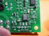
So.....this is missing, why???
Is the module not working???
This is a NOT STUFFED item, nothing to worry....
Regards,
Jan-Peter
Is the module not working???
This is a NOT STUFFED item, nothing to worry....
Regards,
Jan-Peter
my UcD180AD module does not have T21 or T22 either. haven't tried it yet because I'm waiting on supply caps.
well, there you have it from Jan 🙂
well, there you have it from Jan 🙂
Jan-Peter said:So.....this is missing, why???
Is the module not working???
This is a NOT STUFFED item, nothing to worry....
Regards,
Jan-Peter
Still would be nice to know what the purpose of these transistors is/was and why they are not needed.
Best regards
Gertjan
Gertjan,
That is what I really want to know, why some module has it and some other not???????
what's the difference????? May be JAN or Bruno can give some answer.................
PS: The Grande Studio Monitor finally arrived from JAPAN will start setting it up and build the UCD amp to drive it, will send picture and finding to you together with new invented CD hardware call LPCD to you.........
Well, the collector and emitter pins of both T21 and T22 are tied together. The base of T21 is connected to OUTB of the 8620 and the base of T22 is connected to OUTA of the 8620. The collector and emitter of T22 are connected to the negative supply of the 8620, and it appears that the collector and emitter of T21 are as well, although the trace runs under the case of the 8620 so I can't say for sure.
The purpose of these devices, assuming they're pnp transistors, could be to prevent output overshoot below the negative supply rail voltage (plus the drop across the np junction too).
The purpose of these devices, assuming they're pnp transistors, could be to prevent output overshoot below the negative supply rail voltage (plus the drop across the np junction too).
BWRX said:how's this?
Ahhhh, now I see. I saw on my UcD400 modules that the same spots are empty as well. At that time I guessed it was to have the possibility to add a transistor acting as a current source to load the outputs of the AD8620 with a constant current .
Best regards
Gertjan
Ahhhh, now I see. I saw on my UcD400 modules that the same spots are empty as well. At that time I guessed it was to have the possibility to add a transistor acting as a current source to load the outputs of the AD8620 with a constant current .
Ahum......correct. Now you have guessed it, I can tell it. This is a 'hidden audiophile' option for a SST511 😉. But will only work when you have the AD8620 upgrade.
The Grande Studio Monitor finally arrived from JAPAN will start setting it up and build the UCD amp to drive it, will send picture and finding to you together with new invented CD hardware call LPCD to you.........
We are not only very proud that a lot of DIY people like our products, but that we already have some very nice customers where we may act as OEM supplier for their High End Class-D amplifiers. Some are manufacturing very expensive products.....

Jan-Peter
Hmm, is that a kind of "current source" like the sunfire amplifiers have?
Some liked it because of the "slower" and "warmer" sound - actually it added some distortion but some tube lovers enjoyed it very much.
Hmm it must be different, the sunfire's had 2 outputs, voltage and current source, we're talking inputs here 😀
Jan-Peter, on a sidenote, I have some friends that are considering class-d for portable "disco" power... The only thing they are missing is some kind of clip-indicator.
I was looking at this design. - i'm only worried it might affect the sound, because of the feedback circuit used in the UcD's.
Hi,
It's been discussed way back in the 180 thread.
Seems to me that with the AD8620 you might not want that tweak.
Yves you can think of it as a constant current source or an active load, better off as an active load in this case.
A tightly regulated and well filtered auxiliary supply for the front end makes this tweak redundant anyway.
Regards,
Chris
classd4sure said:Hi,
It's been discussed way back in the 180 thread.
Seems to me that with the AD8620 you might not want that tweak.
Yves you can think of it as a constant current source or an active load, better off as an active load in this case.
A tightly regulated and well filtered auxiliary supply for the front end makes this tweak redundant anyway.
Regards,
Chris
Well, I remember Bruno saying in one of these threads that loading the AD8620 with a constant current load to the negative rail was his way to high-end heaven🙂
Anybody tried it? I think most people only tweak the caps, but this could be an interesting one as well.
Best regards
Gertjan
I'm also curious to know if anybody has tried this tweak and, if so, what the results were. Chris asked about it once or twice in the "hotrodding" thread, but those discussions seemed to get de-railed by other controversies.
This is simpler/cheaper to implement than a high quality aux supply (like a super regulator).
Per Tangent's paper on biasing op-amps (http://www.tangentsoft.net/audio/opamp-bias.html), I wonder if two further enhancements would offer any advantage:
1) Using a cascode to further improve current regulation and/or
2) Putting a small resistor between the current source and the op-amp output to isolate the CRD or JFET capacitance (typ 1.5 pF for the J511).
Obviously, these would get into more compexity than just soldering in a single component...
-Bill
hiwi3 said:I'm also curious to know if anybody has tried this tweak and, if so, what the results were. Chris asked about it once or twice in the "hotrodding" thread, but those discussions seemed to get de-railed by other controversies.
This is simpler/cheaper to implement than a high quality aux supply (like a super regulator).
Per Tangent's paper on biasing op-amps (http://www.tangentsoft.net/audio/opamp-bias.html), I wonder if two further enhancements would offer any advantage:
1) Using a cascode to further improve current regulation and/or
2) Putting a small resistor between the current source and the op-amp output to isolate the CRD or JFET capacitance (typ 1.5 pF for the J511).
Obviously, these would get into more compexity than just soldering in a single component...
-Bill
Hi,
I hope this isn't what some commercial guys were laying claim to as having "advanced" the design.... someone even included such a thing in circuits they posted awhile ago 🙂
Tell you guys what, I have the same version and will mod my board thusly as I didn't intend on including the aux supplies + regulators in the very near future.
So if no one else does I'll let you know.
Regards,
Chris
Chris,
Are you going to solder a couple of BF861B for the non stuffed parts or try the other opamp biasing tricks?
Why do you say that biasing is not worth trying with a high quality aux supply? I have a couple of super regulator boards that I want to try for powering the AD8620.
Regards,
Dean
Are you going to solder a couple of BF861B for the non stuffed parts or try the other opamp biasing tricks?
Why do you say that biasing is not worth trying with a high quality aux supply? I have a couple of super regulator boards that I want to try for powering the AD8620.
Regards,
Dean
deandob said:Chris,
Are you going to solder a couple of BF861B for the non stuffed parts or try the other opamp biasing tricks?
Why do you say that biasing is not worth trying with a high quality aux supply? I have a couple of super regulator boards that I want to try for powering the AD8620.
Regards,
Dean
Hi Dean,
Yeah something like that, maybe not that particular one but a flash glance at the data sheet seems like a very decent choice.
I wouldn't bother with any other as the PCB already has the footprint and low noise is important here.
According to Bruno's explanation of what is really occuring with that tweak, it has next to nothing to do with "Class A biasing" in that cross over distortion isnt' the problem as seems to be the common thought. His post will explain it better if you can find it, but it has to do with how the op amp is being compensated, always leaves you with one rail that has lower PSRR than the other, usually you can see this on the data sheet.
To that respect you dont' always use this tweak as commonly thought by tying the load to the negative rail. Maybe that's what JP meant when he said you needed the AD op amp for this, the 5532 might require being tied to the positive rail.
Anyway the point is, if you have a _very_ quiet supply, increased PSRR then becomes redundant. But at the same time it's a 2 cent part and if it makes you feel better why not?
Increased operating temperature of the amp is the only downside and I can't see that being a very big deal.
Put it this way when I do add the aux supplies, since I'll already have the active load in place I won't bother removing it, but I'm sure it's more of a bandaid and the real tweak would be the aux supplies and regulators like yours 🙂
I hope I'm not babbling too much considering the hour.
Regards,
Chris
hiwi3 said:I'm also curious to know if anybody has tried this tweak and, if so, what the results were. Chris asked about it once or twice in the "hotrodding" thread, but those discussions seemed to get de-railed by other controversies.
This is simpler/cheaper to implement than a high quality aux supply (like a super regulator).
Per Tangent's paper on biasing op-amps (http://www.tangentsoft.net/audio/opamp-bias.html), I wonder if two further enhancements would offer any advantage:
1) Using a cascode to further improve current regulation and/or
2) Putting a small resistor between the current source and the op-amp output to isolate the CRD or JFET capacitance (typ 1.5 pF for the J511).
Obviously, these would get into more compexity than just soldering in a single component...
-Bill
I don't think that 1.5pF would do any harm, the capacitance of the output pads of the opamp is probably already higher than that, let alone the traces on the PCB.
Best regards
Gertjan
- Status
- Not open for further replies.
- Home
- Amplifiers
- Class D
- UCD180AD missing transistor?????