Hello,
If you want to switch your amps on and off only by a front panel power switch, just connect /ON to the amp power supply ground.
George
If you want to switch your amps on and off only by a front panel power switch, just connect /ON to the amp power supply ground.
George
Just to clarify. You connect the "ON" line to ground to make the amps switch on... In the case of the Zappulse units you connect a similar connection to ground to turn them off (well into standby).
On a related note: Can anyone describe what they might do to have remote start and stop of these two types of amp? ie, I have a homebuilt pre-amp which has some spare outputs that I could use to do remote switching on/off all my amps.
Since they each flip in different directions, and also that connecting all the amp grounds together is unlikely to be clever, anyone got any clever ideas for using a relay to remotely flip em on and off?
Is it best to have a design where power needs to be applied continuously to some input line to switch the amps on? If the connection is removed then power goes away. Or perhaps it's better to have a three line input and pull one switch each way to make it flip-flop (with the default perhaps being "on").
Any thoughts on a nice design for this (preferably quite simple since it's going to have to be retro fitted in my case...)
Ed, what is the latch supply on the preditor? I put a link from my UCD modules to the Power GND and the blue light came on after a couple of seconds. How have you wired your?
Cherhit, thanks.
Cherhit, thanks.
Maxlorenz;
Would you be kind and tell us, humble beginners, if we need smaller caps after these large cans?[?QUOTE]
No not necessary, better use one good cap.
Wytco;
Hi I am just about to connect up my UCD180's but I am a bit confused about how to connect the /ON (internal pull-up) pin?
I want to switch my amp on via a mains switch on the front panel. What should I do?
You can put the /ON always on the GND line, but you can have some noises when you switch the amp off. Because the capacitors are discharging quit slow so you don't have a fast/sharp moment when the amps switch off. Please use the circuit in the attachment, every small NPN transistor will work. AC1 and AC2 are the secondairy voltages.
Regards,
Jan-Peter
Attachments
Jan Peter, thanks for that, I watched the capacitor discharge on my DMM and as you suggest it takes several seconds, however I want to get my amp running so for the moment I will just do it from the gnd. 🙂
Well its up and running first impressions after about 30 minutes of listening, very dynamic and clear, slightly sibilant but that may be my speakers. Overall very very nice sound.
Modules are running very cool and so far no problems at all.
The switch on and off thump is minor less that the Music Fidelity I was using before.
Modules are running very cool and so far no problems at all.
The switch on and off thump is minor less that the Music Fidelity I was using before.
Here is a picture of my amp, its built into an old Music Fidelity case but this is temporary.
The picture is over a Meg so its a link :-
wytco0 amp
The picture is over a Meg so its a link :-
wytco0 amp
How does the UdC180 do with highly capacitive loads? Has anyone used these modules to drive full range electrostatic speakers or high-capacitance speaker wire, like Polk Cobra Cable? TIA, mac.
wytco0: Have you thought about using shorter wires...? Probably you could turn the PS around and make those wires extremely direct. Also, I'm sure the source and speaker wires would prefer to be a little shorter?
Anyone: is there any point seperating the modules? Do they interfere in any respect?
Anyone: is there any point seperating the modules? Do they interfere in any respect?
Wytco,
Nice picture, but indeed try to make the wires a little bit short. It's no problem, but it looks nices and it is always better.
Mac,
The UcD180 works ok with capacitive loads. In a way the amp has a capacitor of 680nF at the output.........😀
Regards,
Jan-Peter
Nice picture, but indeed try to make the wires a little bit short. It's no problem, but it looks nices and it is always better.
Mac,
The UcD180 works ok with capacitive loads. In a way the amp has a capacitor of 680nF at the output.........😀
Regards,
Jan-Peter
Ed. yes I am planning to make them shorter but this is just a test setup, the main thing I was doing here was making sure that all pairs of wires are the same length. In the longer term I will rebuild it as dual mono.
The only ones I am a bit concerned about is the input wires they may be a bit long and not ideal they are stripped out of a bit of Cat 5 Network cable. I have a feeling they may be contributing to the sibilance I am getting.
The only ones I am a bit concerned about is the input wires they may be a bit long and not ideal they are stripped out of a bit of Cat 5 Network cable. I have a feeling they may be contributing to the sibilance I am getting.
My advice also is to tidy up in the case. As short wires as possible and keep signal, speaker and power wires well separated. I'll believe this is even more important since this is a class D amp.
I wonder if the cooling is sufficuent for the rectifiers, maybe if you play "normal" music. Notice that one of the rectifiers has less cooling than the other one.
Otherwise I think the UcD modules looks real good and professional.
I wonder if the cooling is sufficuent for the rectifiers, maybe if you play "normal" music. Notice that one of the rectifiers has less cooling than the other one.
Otherwise I think the UcD modules looks real good and professional.
Jan-Peter said:
You can put the /ON always on the GND line, but you can have some noises when you switch the amp off. Because the capacitors are discharging quit slow so you don't have a fast/sharp moment when the amps switch off. Please use the circuit in the attachment, every small NPN transistor will work. AC1 and AC2 are the secondairy voltages.
Regards,
Jan-Peter
Regarding the pull-up resistor R16; if there are already pull-up resistors on the UCD180/UCD400 on the /ON signal then is this resistor is optional ?
If not, can a +12V supply be used instead of a +15V ?
Nickiwicky;
Regarding the pull-up resistor R16; if there are already pull-up resistors on the UCD180/UCD400 on the /ON signal then is this resistor is optional ?
If not, can a +12V supply be used instead of a +15V ?
Indeed you are completly right, there is already a pull up resistor in the UcD180/400. So you can forget the +15V line by the transistor. A simple open collector output is already sufficient. There are all protection diodes inside the UcD180/400 so a higher voltage (max. 50VDC) is also no problem.
Regards,
Jan-Peter
Jan-Peter said:
Indeed you are completly right, there is already a pull up resistor in the UcD180/400. So you can forget the +15V line by the transistor. A simple open collector output is already sufficient. There are all protection diodes inside the UcD180/400 so a higher voltage (max. 50VDC) is also no problem.
Regards,
Jan-Peter
All this stuff can be added directly in the power supply circuit?
See the inclosed pcb.
Attachments
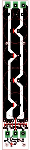
Steff,
The standby part is OK! But I should make a real star point where you connect all GND. Bottom is GND transformer input and top is GND to the amplifier.
Regards,
Jan-Peter
The standby part is OK! But I should make a real star point where you connect all GND. Bottom is GND transformer input and top is GND to the amplifier.
Regards,
Jan-Peter
Jan-Peter said:Steff,
The standby part is OK! But I should make a real star point where you connect all GND. Bottom is GND transformer input and top is GND to the amplifier.
Regards,
Jan-Peter
Hi Jan-Peter,
No sure to understand. You say that the standby circuit is not connected to the right GND !
Can you be more detailed?
(the pcb is not yet done)
Stef,
The point where the lines from the both capacitors are connected with the center point of the transformer must be a star point. On this centerpoint the voltage is 0V with no 100Hz voltage.
The current of the AC-detection is very small, so you can connect where you like.
Check this link: www.hypex.nl/pcb.pdf
Jan-Peter
Jan-Peter said:Stef,
The point where the lines from the both capacitors are connected with the center point of the transformer must be a star point. On this centerpoint the voltage is 0V with no 100Hz voltage.
The current of the AC-detection is very small, so you can connect where you like.
Check this link: www.hypex.nl/pcb.pdf
Jan-Peter
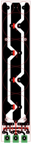
If I well understand, the GND of "standby circuit" should be connected to the ground at the output of the PSU (as a star !).
May be the best is to have the standby circuit on another pcb.
Curently, the psu project is like this. It will fit inside a 1U cabinet. Have a looks on the pictures.
185 x 38 mm
Attachments
- Home
- Amplifiers
- Class D
- UCD180 questions