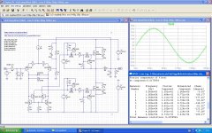
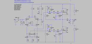
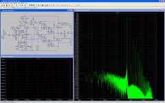
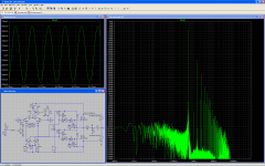
Hello, I had great fun simulating the UcD module Philips UM10155. Can somebody check the waveforms ?
Attachments
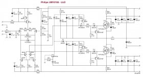
In the philips circuit, R9 330ohm controls deadtime. As default the philips eval module comes set to high efficiency mode (long deadtime).
Play around with the value of this resistor and see what changes that brings in simulation THD.
Also play around a bit with the resistor in the phase lead network and see what changes a increase or decrease in switching frequency gives in simulation THD.
Play around with the value of this resistor and see what changes that brings in simulation THD.
Also play around a bit with the resistor in the phase lead network and see what changes a increase or decrease in switching frequency gives in simulation THD.
Thank you, indeed R9 value is critical. A low value induces cross conduction spikes. A high value adds deadtime, preventing cross conduction spikes. Past the optimal value where the cross conduction spikes get eradicated, the distortion increase. Actually the lowest distortion occurs when there remain visible crossover spikes, same spike magnitude as the coil ripple current at idle. EMI will be badly impacted. This is of course on simulation. Don't know if the real world behaves this way.In the philips circuit, R9 330ohm controls deadtime. As default the philips eval module comes set to high efficiency mode (long deadtime). Play around with the value of this resistor and see what changes that brings in simulation THD.

I think that you better can judge performance, by designing a single PCB containing everything, including the comparator/modulator, power MOSFETs, local power supplies, filtering capacitors and filtering coil. Will you try this? Please specify Philips and NXP components all-round. I'm willing to order PCBs for building such amp. Supply rails say +42V and -42V, no more.
I have a test power module that takes the differential signals in from the PUT (Prototype Under Test) IE i dont design a full amp board until i i have prototyped the modulator section and tested it.
Have you considered an epoxy prototyping board for the comparator/modulator?I have a test power module that takes the differential signals in from the PUT (Prototype Under Test) IE i dont design a full amp board until i i have prototyped the modulator section and tested it.
Attachments
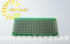
That is what i was gonna solder it together on. That cadded template was so i know beforehand how to place the transistors and wires.
Either way heres the layout for the ic based UcD, which was ordered today from seedstudio, am currently listening to music on the prototype.
Either way heres the layout for the ic based UcD, which was ordered today from seedstudio, am currently listening to music on the prototype.
Last edited:
Oops, sorry, I missed R10. Current is thus OK. Can you please run the same simulation, without the cascode? I would like to compare the noise floor and distortion.
Indeed. The cascode worsens the noise by 6 dB. Is that an implementation issue?
Have you checked the THD?
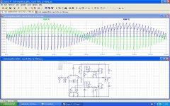
I got interested by a cascode as it isolates the differential pair from the switching transients. Plot the current wavevorms in the differential input stage. Without the cascode, the differential pair collector currents are far from clean. I'm thus expecting a better audio quality with the cascode.
A THD decrease with the cascodes, would confirm such theory. Can you please check?
Have you checked the THD?
I got interested by a cascode as it isolates the differential pair from the switching transients. Plot the current wavevorms in the differential input stage. Without the cascode, the differential pair collector currents are far from clean. I'm thus expecting a better audio quality with the cascode.
A THD decrease with the cascodes, would confirm such theory. Can you please check?
Could be zener noise, implementation noise, transistor noise, who knows.
Will keep investigating.
Will keep investigating.
Here is a compilation of tests, with and without cascode, different voltage ceners in the cascode, and also an iteration of Anaview's "Active Pole Control"
class d circuits comparison - Imgur
class d circuits comparison - Imgur
Regarding D4 and D5, aren't they supposed to be Schottky diodes?
Cascode seems to bring THD from 0.56% to 0.48%, as small improvement.
Apparently, cascode voltage can by anywhere between 10V to 33V.
I think you can remove D4 and D5 with the cascode.
Have you tried comparing the noise of a Zener-based cascode, with an ideal voltage source-based cascode?
I'd like to know the LTspice settings & FFT viewer settings for plotting the noise spectrum, like you did, for reproducing the plot on my side.
I'm astonished by the performance of the integrator as error correction feedback, exploiting the virtual ground error signal. It appears to divide THD by 10.
Does it work in the real world?
Currently, I can't find info on internet about it. Is it brand new?
Looking at it, I see a A.M. Sandman reminiscence (October 1974 in Wireless World). http://www.keith-snook.info/Wireles...4/Reducing Amplifier Distortion - Sandman.pdf
Looking at the output coil, I see another improvement possibility, which is the P.J. Walker (aka Quad 405) arrangement described in December 1975 in Wireless World.
Last edited:
Supposedly it minimizes both linear and non linear distortion, according to the claims in the patent.
A link: https://www.google.se/patents/US201...X&ei=bBGpUYCZPOeOiALz5oHABQ&ved=0CDcQ6AEwADgK
I got the idea to try it after looking through patents filed by Patrik Boström, the CEO of Anaview in Helsingborg Sweden.
A link: https://www.google.se/patents/US201...X&ei=bBGpUYCZPOeOiALz5oHABQ&ved=0CDcQ6AEwADgK
I got the idea to try it after looking through patents filed by Patrik Boström, the CEO of Anaview in Helsingborg Sweden.
US20120235742 from Patrick Boström is a remakable patent indeed, and very recent. Thanks for pointing it. The patent would have been clearer if Fig. 3 was representing the actual comparator propagation delay, duly located in the transmission path, instead of relying on R44 and C19 as quick and dirty way for taking such effect in consideration.
One may try simulating the limiter/clamp of Fig. 4.
There is small annoyance however. The input impedance gets quite small now, say 1K or so. Need a buffered volume pot.
I went looking the Anaview website. http://www.anaview.com/index.php?page=custom-design
It reads : "Unique Anaview control IC - Anaview has developed an optimized IC to control the developed amplifiers. This IC is state of the art and it has several unique features. Up to 600W/4ohm capability".
"In 2009, two patent applications were filed, that brought Anaview's technology to a new level. APC (Adaptive Pole Control) and AMS (Adaptive Modulation Servo). Both are circuits that strive to optimize the behaviour of basic globally self modulated Class D topologies without significantly increasing the parts count. January 2011, Anaview merged with Norwegian Abletec, which aimed to increase their product offerings from being only switch mode power supplies, to including also audio power modules. January 2013, Anaview is back in business again."
Is US20120235742 dealing with APC, or AMS?
What IC are they talking about? What are the features? APC? AMS?
Is it available?
Last edited:
- Status
- Not open for further replies.
- Home
- Amplifiers
- Class D
- UcD Philips UM10155 LTspice simulation