Hello all,
I'm working on a UCD type amplifier.
Got my proto pcb made with the help of LTspice.
It's based on the UM10155.
My problem is that in LTspice everything works great and its oscillating around 400 kHz, but in reality i get oscillation around 1.1 MHz and the mosfet driving looks like ****....
I know that simulations and real world can diver greatly but this is way off !
What i understand from UCD is that the feedback network mainly determines the switching frequency by pushing the transfer function(s) through 180 degree phase shift.
I must say that i'm relatively new to the UCD topology and have a lot to learn and learned a lot allready...
But maybe someone has some tips on where to look at...
Or someone has build a UCD like amplifier and can give me hints/tips to look at.
Cheers, and thanks...
If you post your schematic with the components you are using, it would better. In my experience (little), you can have wrong R and C values or missing a connection/wrong connection in the feedback loop. Are you testing on breadboard or you have a pcb?
Hello Vinzzz,
Thanks for the reply,
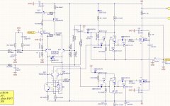
I attached the schematic.
I have this on a pcb and not a breadboard.
The -78V is the +12V referred to -B1, dont mind the capacitor C27 its wrongly connected.
Its a second order mfb differential arrangement.
The aim was around 400 kHz oscillation but it gives 1.1MHz...
Maybe you could see something wrong...
Thanks...
Thanks for the reply,
I attached the schematic.
I have this on a pcb and not a breadboard.
The -78V is the +12V referred to -B1, dont mind the capacitor C27 its wrongly connected.
Its a second order mfb differential arrangement.
The aim was around 400 kHz oscillation but it gives 1.1MHz...
Maybe you could see something wrong...
Thanks...
Attachments
I don't see something wrong (but I'm not an expert), I think it should work. Sorry for the stupid question, but have you connected the load and input? Have you measured L value? Remember that pcb plays an important role for correct working. Have you tried to lower the switching frequency by increasing L and C values? You can try with 33uH and 1.5uF.
PS: I suppose you're testing it with low psu voltage. If not, I recommend you to start with low rail voltage (such as +/-30v).
PS: I suppose you're testing it with low psu voltage. If not, I recommend you to start with low rail voltage (such as +/-30v).
Hello ViNzZz,
Thanx for the reply.
At first it didnt work, then i removed the feedback loop and put a fixed triangle wave at the input of the diff. amp. and grounded the other.
That way i checked both mosfet drivers to make sure that they work properly.
It turned out that one transistor was broken...
When i repaired it and closed the loop (same loop as UM10155) it works.
So i'm a little bit further but have still a lot to do...
Greetz,
Hello Pafi,
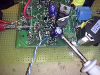
28 = PCB
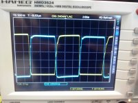
29 = mosfet waveforms.
Pcb is a real mess momentary, now working on low voltage because i have great difficulty to get the mosfet driving working properly.
THD at around 1.5 %.
But i'm glad it works, so i can work on it further...
Greetz.
28 = PCB
29 = mosfet waveforms.
Pcb is a real mess momentary, now working on low voltage because i have great difficulty to get the mosfet driving working properly.
THD at around 1.5 %.
But i'm glad it works, so i can work on it further...
Greetz.
Attachments
- Status
- Not open for further replies.
- Home
- Amplifiers
- Class D
- UCD amp oscillation troubleshooting