Hi manoj
Think you mistaken me with smbody🙂
I never used " the red rings" , only ferrite , mostly EI or ER.
Hi Dimonis
PLS SEND ME T106-2 CORE; IS IT POSSIBLE TO SEND ITEM TO INDIA???
I HAD ONLY T38-26(YELLOW WHITE)
Think you mistaken me with smbody🙂
I never used " the red rings" , only ferrite , mostly EI or ER.
Hi all
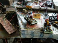
completed my PCB and waiting T106-2 core,before it comes i wound a T38(i think its T37)yellow white core pls check my photo
Agree with CPX , do not even try using yellow\white cores , it's the T...-26 .
😉T38 it's a ferrit , and its green.😉
Yes..there are many cores you can use:red(t106-2); red/black(t106-14); blue/yellow(t106-17);yellow(t106-6); .
Yes , a good choice , but as for me i can't get any of whose. So i use gapped ferrit🙄
IR at the begining used "the red ones" , but from iraudamp4 they prefer the ferrit Sagami coils!
You can find some on ebay...
2x T106-2 Micrometal Torroid Red 1.06" Dia Ham Radio | eBay
They ship to russia 🙂.
2x T106-2 Micrometal Torroid Red 1.06" Dia Ham Radio | eBay
They ship to russia 🙂.
You can find some on ebay...
2x T106-2 Micrometal Torroid Red 1.06" Dia Ham Radio | eBay
They ship to russia 🙂.
Thanks , i saw these.Also T130-2 . I can get in Russia cheaper and quicker .
Yes and i want to try them , but i have an amount of ferrite.😀
Maybe sometime later?😀
They are better for EMI.Unless you have complete enclosed gapped ferite inductor(wires not visible outside) which is better you must try those.
Wrong you are , if the gap is only in the center leg , the EMI is shielded by the winding, ye it'll be hotter , but EMI will be reduced.They are better for EMI.Unless you have complete enclosed gapped ferite inductor(wires not visible outside) which is better you must try those.
In ferrite the EMI is emitted only from the gap.
And the ironpowder core emite all way round due to the microgaps of the powder.
P.S. In DIY nobody bothers about EMI , so and I.😎
Last edited:
Ok..i will do some further research on that😕..but what i know is that EI/EE/ETD ferite or will have much more EMI than iron powder toroids..
You will care alot about emi when after starting your amplifier you will lose all radio reception😀...for me a portable radio half a meter from the amplifier has to work normaly.Also emi from inductor increases THD and IMD..so is very important for diy segment also.
You will care alot about emi when after starting your amplifier you will lose all radio reception😀...for me a portable radio half a meter from the amplifier has to work normaly.Also emi from inductor increases THD and IMD..so is very important for diy segment also.
Last edited:
Ok..i will do some further research on that😕..but what i know is that EI/EE/ETD ferite or will have much more EMI than iron powder toroids..
EI - yes , because the gap is on the edge of the winding
Very good for inductors are RM and PQ
Attachments
Also emi from inductor increases THD and IMD..so is very important for diy segment also.
If the layout is bad enough for it😀
You will care alot about emi when after starting your amplifier you will lose all radio reception😀...for me a portable radio half a meter from the amplifier has to work normaly.
The emi from the conductors and wires will be more significant than from inductor🙄
Emi from the inductor wires..yes...i though alot how to shield the inductor and made several experiments but without good results....the ones you posted i never tried..maybe in the next version..
Emi from the speaker wires can be reduced also by using an additional low pass filter after the amplifier.
Emi from the speaker wires can be reduced also by using an additional low pass filter after the amplifier.
the LM311 + phase inverter parts in the first post of this thread, are still correct?
Or, which is the latest schematic update for that section? 🙂
Or, which is the latest schematic update for that section? 🙂
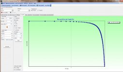
Here's a good prog for calculating and designing a SMPS transformer
Where?
sorry
Forgot to paste
Here we go - http://www.diyaudio.com/forums/powe...ormer-design-tool-ver-4000-a.html#post2953096
Forgot to paste
Here we go - http://www.diyaudio.com/forums/powe...ormer-design-tool-ver-4000-a.html#post2953096
sorry
Forgot to paste
Here we go - http://www.diyaudio.com/forums/powe...ormer-design-tool-ver-4000-a.html#post2953096
Thanks, No problem 🙂
Hi Manojtm,
Nice photo#1836 on page 184.Where to find P.c.b. Layout and circuit diagram of this nice amp you made. I can see three pairs of mosfet in your photo. How much wattage of this Amp.Please post Schematic and Pc.b copper side in P.d.f.
Regards
Vedmitra Sharma
Nice photo#1836 on page 184.Where to find P.c.b. Layout and circuit diagram of this nice amp you made. I can see three pairs of mosfet in your photo. How much wattage of this Amp.Please post Schematic and Pc.b copper side in P.d.f.
Regards
Vedmitra Sharma
- Home
- Amplifiers
- Class D
- UCD 25 watts to 1200 watts using 2 mosfets