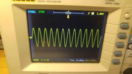
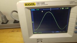
As the title states, I have this 2000X, someone had given me to look at. The complaint is that there is audible distortion. I played it, and it's very faint, but definitely noticeable. I checked out a sine wave waveform through the amp, and it looks fine, for the most part. However, if I zoom in on the waveform pretty close (200mv/div), I can see right around zero, a VERY small 'notch' that I've understood may be indicative of a bias issue. The amp draws 0.1A at idle, which seems pretty low (I found somewhere a review that says the amp draws 1A at idle).
My question is, how is this amp biased? There doesn't seem to be a pot for it anywhere. Is there any way to adjust that?
My question is, how is this amp biased? There doesn't seem to be a pot for it anywhere. Is there any way to adjust that?
Attachments
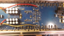
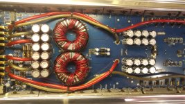
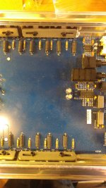
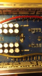
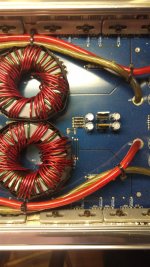
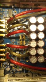
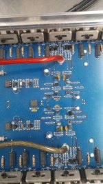
Either way, here are some pictures of the board. Even if we don't need them, might be good for someone in the future. five are one orientation, the two are the other. I did that to try and make sure I captured as many details as possible. Please let me know if any more or more detailed pictures will be necessary, I resized them to fit here. I still have the originals, if we need.
Attachments
For the bias transistor between the output transistors, does it have one resistor that connects between it's base and collector and another that connects between its base and emitter?
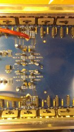
Do these pictures by chance help at all, or is it something I'll have to follow around to determine? I'm actually not positive which one we are talking about exactly. Is it the one labelled Q408 in there? Or Q410/411?
Attachments

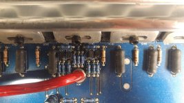
The bias transistor is between Q410 and Q411. You'll have to use your meter to determine the connections to the resistors.
The red-green value needs to be decreased or the green-blue needs to be increased. Change them just slightly or use a potentiometer in place of one of the resistors and adjust the bias by monitoring the idle current.
After this is done and you get clean audio, you need to drive the amp to thermal shutdown, monitoring the idle current as the amp heats up to confirm that the idle current hasn't changed significantly.
After this is done and you get clean audio, you need to drive the amp to thermal shutdown, monitoring the idle current as the amp heats up to confirm that the idle current hasn't changed significantly.
Thank you for your reply! Will it matter which of the two I opt to go with? I'm just curious if it needs a 'minimum' resistance and it would be better to go up, or it has a 'maximum threshold', and it would be better to decrease the value of one instead. Just want to learn for future reference.
I don't know if changing one or the other will be best. If you just barely have to change the value, it probably won't matter. If you need to make a significant change, it would probably be better to change the base to collector value.
Okay, so I gave it a shot -- I dropped the red/green value down to as far as 500, with no results; still 0.1A current draw at idle. Should I try raising the green/blue value instead, or would there possibly be something else to look into if dropping the value that far had no impact whatsoever?
You can go lower if you have the transistors clamped down and very carefully watch the idle current. This won't be a permanent solution. It will simply be used to confirm that the bias circuit can increase the idle current. If you have a B+ current limiter, use it.
Hello again. I got distracted with other projects recently, but am now back to working on this amplifier. I tried decreasing the red-green resistance to almost-zero (paralleled resistors as low as 100 ohm in line with the 1k resistor there), and still got no results. Still floating between 0.0 and 0.1A, usually closer to 0.0A idle. The amp does play audio on demand, and the wave doesn't really look mangled that I can see, but you can definitely hear that it does not sound quite right. Any further suggestions from this point?
The bias circuit may not have enough range. If you disconnect one of the b-c resistors, does the amp draw excessive current? Be careful, it could damage the outputs if you leave it on too long, even if they're clamped down.
Well, I disconnected one of the resistors (specifically the purple leg of the resistor marked with blue and purple identifiers), and still 0.0-0.1A idle current.
It appears that there isn't enough bias current through the differential amplifier section. What is the voltage on the power supply pins of the op-amps?
The only op-amps that I recognized were the two on the far end of the amp, near the controls and input. They are as follows:
TL072CP
1.)
Pin 4 (Vcc-): -15vDC
Pin 8 (Vcc+): +15vDC
2.)
TL074CN
Pin 4 (Vcc+): +15vDC
Pin 11 (Vcc-): -15vDC
They are not 'exact' values, but as close as I could estimate with an oscilloscope (it has a finer point than I have at the moment for my multimeter, and I have it mostly insulated). It appeared to be spot on, or maybe with in .1v tolerance.
There have been instances where low regulated voltages have caused this problem but that doesn't appear to be the case here.
To increase the bias in the differential amp stage, you would need to reduce the value of the resistors in series with the regulated supplies. In the attached diagram, they are R91 and R106. Reduce the values gradually until the amp starts to draw more current.
To increase the bias in the differential amp stage, you would need to reduce the value of the resistors in series with the regulated supplies. In the attached diagram, they are R91 and R106. Reduce the values gradually until the amp starts to draw more current.
Attachments

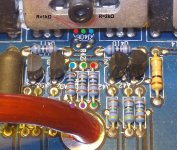
Hello again. I'm a touch unsure of where 'exactly' I'm looking. I did find that these resistors have + and - 15v (one on each) on one side, and ~ +/-.5v on the other side. They are 10k resistors, and I did test continuity to one leading over into the area we had been working prior, one of the three resistors that goes to the bias transistor (unfortunately I did not record which one specifically). Would these be the resistors in question? I'd much prefer to ask before just 'doing'.
Attachments
- Status
- Not open for further replies.
- Home
- General Interest
- Car Audio
- U.S. Amps 2000X - Bias Issue / Adjustment?