Last year, I designed and built a 6J5-45 parafeed headphone amplifier, one of my first tube DIY projects. In a lot of ways it was a speaker amplifier adapted for headphones with a cold bias point. Over time I regretted not building it for speakers with a switchable headphone output.
Well yesterday I rectified that (no pun intended) and rebuilt the amplifier for speakers with a new mains transformer to get the full 1.5W out of the 45 😎
This will live in a small bedroom setup with a pair of Klipsch KG 1, so 1.5W is plenty for that space.
Anyway, I like to share photos of my completed projects, so here are some pics and a general schematic (final component values may be slightly different). Nothing fancy, a simple design, but the sound is quite nice!


Thanks for checking it out.
Well yesterday I rectified that (no pun intended) and rebuilt the amplifier for speakers with a new mains transformer to get the full 1.5W out of the 45 😎
This will live in a small bedroom setup with a pair of Klipsch KG 1, so 1.5W is plenty for that space.
Anyway, I like to share photos of my completed projects, so here are some pics and a general schematic (final component values may be slightly different). Nothing fancy, a simple design, but the sound is quite nice!
Thanks for checking it out.
Nice build ... as usual. 🙂
I am always envious of seeing your metalwork.
I think it was unnecessary to use first stage HT with CRC if you are only worried about separation.
The CCS as anode load has -at least- 60dB PSRR.
To reduce this CCS dissipation, its HT would be no more than 2x Ua, i.e. 380V.
I am always envious of seeing your metalwork.
I think it was unnecessary to use first stage HT with CRC if you are only worried about separation.
The CCS as anode load has -at least- 60dB PSRR.
To reduce this CCS dissipation, its HT would be no more than 2x Ua, i.e. 380V.
Last edited:
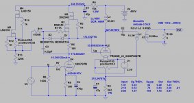
Thank you 🙂 yes I should increase the last RC to save the CCS some heat, thanks for pointing it out. I left most everything as it was when I was a little less experienced, the power supply is probably overkill, CLCRC but with the CCS everywhere, likely could be CRCRC!
Here ya go, simple single rail CLCRC. Mains transformer is a custom job from Sowter, 380VAC 161mA B+ winding, 45 filament windings are on the transformer with screens. The last RC resistor will be changed to 5K, it was 1K.

Superb build and stunning quality of the metalwork.
Very nice looking pics. Thank you!
P.S. The mains switch reminded me of something own..
Very nice looking pics. Thank you!
P.S. The mains switch reminded me of something own..
Attachments

Last edited:
Thank you 🙂 before I get too many compliments on the metalwork, let me point out that I cannot take credit for it! The chassis layout / design was done by me in AutoCAD software, while the machining itself was done by Landfall Systems, Dave over there does very nice work and is in the process of getting a powder coating operation up and running for a "one stop shop" for amplifier chassis.
Nice build!
Could you make that a DC coupled amp by loosing C3, R5 and R6? You might have to tweak the operating point(s) of the tubes a bit, but...
Could you make that a DC coupled amp by loosing C3, R5 and R6? You might have to tweak the operating point(s) of the tubes a bit, but...
Direct coupling the circuit is an interesting idea, it had not occurred to me to try it, thanks for the suggestion! Seems plausible, let me work on some simulations and return 🙂 I think if I were to attempt it, I might swap the 6J5 CCS load for a gyrator.
Well I think direct coupling without completely overhauling the circuit is going to be impractical, the issue being I will run out of B+ for the peak swing of the 45 since the 45 cathode voltage will need to be increased to the equivalent voltage of the 6J5 plate / 45 grid. Since I am using a CCS load as opposed to a choke, the B+ has to cover the full peak swing of the output along with the dropout voltage of the CCS.
Say I were to direct couple with 80V on the grid of the 45 and the cathode at 130V and cooled off the 45 bias point to 250Va / 35mA Ia / -50Vg - that would put the 45 plate at 380V with only ~120V headroom to cover the peak swing of the 45 and the CCS dropout voltage, which won't work. Bummer! Could be done easily with a choke, but would increase the footprint of the amplifier, keeping things somewhat compact was a priority for this design.
Well thanks for the idea anyway, mbrennwa!
If you use direct drive and choke instead of CCS, must be sure that static operating point of #45 remains steady, i.e. -at least- first stage anode voltage drift has been minimized.L0rdGwyn said:Could be done easily with a choke
The proper DC value setting option is also important.
"Gyrator" loading is satisfactory solution.
Attachments
Last edited:
Yes! If ever I was to do a DC coupled 45 with choke anode load, I would use a gyrator on the driver to stabilize 45 grid. I plan to design a gyrator PCB very soon to use in future designs, something similar to what you have shown in your schematic, inspired by Ale Moglia's gyrator. I do wonder how the sound compares vs. a typical cascode CCS anode load in equivalent circuits.
If we build from modules, similarity is inevitable. 😛
I use Ale's gyrator for the beginning, one of my preamp still use the early one prototype.
I use Ale's gyrator for the beginning, one of my preamp still use the early one prototype.
Great job, looks fantastic. Well done.
About 10 years ago I built a 45 amplifier which has a 6J5 (half 6SN7) with a CCS anode load. I morphed it to a hybrid mu follower (aka gyrator) and DC coupled to the grid. Improved sound for sure, better performance of the driver and also able to handle the grid of the 45 effectively. Then moved to a 7193, much better sound. LED bias (although I’d use SiC now) was much better than resistor only in my experience.
Keep experimenting, it’s fun!
Cheers
Ale
Here is another direct-coupled 45 parafeed idea that was developed here on diyAudio a while ago. It's very similar to the one in post #13. I have most parts, but I never got around to actually build it...
Excellent, thanks. If I were to do it again, and were not rebuilding an old design, perhaps I would choke load and direct couple in a similar design, I'm sure the clarity and imaging are phenomenal.
If we build from modules, similarity is inevitable. 😛
I use Ale's gyrator for the beginning, one of my preamp still use the early one prototype.
I have not started experimenting with gyrator loads just yet, but it is next on the to-do list. I may use as the load for the pentode gain stage of my 801A A2 amplifier, the design is getting close to being finalized!
Great job, looks fantastic. Well done.
About 10 years ago I built a 45 amplifier which has a 6J5 (half 6SN7) with a CCS anode load. I morphed it to a hybrid mu follower (aka gyrator) and DC coupled to the grid. Improved sound for sure, better performance of the driver and also able to handle the grid of the 45 effectively. Then moved to a 7193, much better sound. LED bias (although I’d use SiC now) was much better than resistor only in my experience.
Keep experimenting, it’s fun!
Cheers
Ale
Thanks, Ale. I hadn't heard the 7193 was an improvement over its 6J5 cousin, I will have to look into it. From some limited experiments, I found I preferred the sound of an unbypassed cathode resistor as opposed to LED (HLMP6000), but I will need to revisit that at some point.
In these direct-coupled 45 designs, is it necessary to provide any protection for the 45 grid during startup as the input tube comes up to bias?
Thats a good question, and I have to admit that I have not thought about it. I would hope the cathode bias of the 45 tube would limit the current at startup, but I would have to look into this more carefully. Maybe others who have actually built something like this may provide some better insight.
- Home
- Amplifiers
- Tubes / Valves
- Type 45 Parafeed Rebuild Complete