I'm trying to use the Vbe multiplier (d) shown in http://www.renardson-audio.com/B-amp.html but I'm not sure which one is the "sensor" transistor.
D. Self refers to the same circuit in his "Audio Power Amplifier design" 6th edition book: "The first transistor is the sensor." But cant say which is the "first".
I would appreciate some help.
Thanks.
D. Self refers to the same circuit in his "Audio Power Amplifier design" 6th edition book: "The first transistor is the sensor." But cant say which is the "first".
I would appreciate some help.
Thanks.
Attachments
I'm thinking this one:

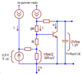
You definitely want the transistor I've marked in red to track the temperature of the output devices. That's also the first when viewed left to right. I do agree about the ambiguity in the language, though.
The bottom transistor is the VAS.
Tom
You definitely want the transistor I've marked in red to track the temperature of the output devices. That's also the first when viewed left to right. I do agree about the ambiguity in the language, though.
The bottom transistor is the VAS.
Tom

Agree with Tom. Q2 is inside Q1's NFB loop, and obeys Q1's commands.

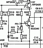
In a later version (confusingly mirrored):

Don't believe me? I wouldn't. EXPERIMENT. But simplify. 9V battery, 3k resistor. Creme Brulee Torch (or lighter, or soldering iron...)

Meter the "??" point to ground/0V. Does it drop when you cook Q1? Q2? Hypothesis: Q1 has the most effect, Q2 almost none except by blow-by heat getting to Q1 (some heat deflector may clear this up).
In a later version (confusingly mirrored):
Don't believe me? I wouldn't. EXPERIMENT. But simplify. 9V battery, 3k resistor. Creme Brulee Torch (or lighter, or soldering iron...)
Meter the "??" point to ground/0V. Does it drop when you cook Q1? Q2? Hypothesis: Q1 has the most effect, Q2 almost none except by blow-by heat getting to Q1 (some heat deflector may clear this up).
Last edited:
I've never been particularly happy with conventional Vbe multipliers. It would seem that the adjustment pot alters the "volts per degree" slope, and the volts setting is secondary. IOW it is changing the gain rather than the offset. The setting might be right for the temp you set it at, but as it heats up it might either dig in too hard or dry out, depending on the pot setting. Thoughts?
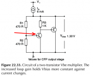
The voltage gain determines the voltage drop per degree. For the emitter base junction this is about -2mV/K. If the gain is g, the total voltage drop would be -2.g mV/K. The non zero base current is a source of error which is kept low by using transistors with sufficiently high gain.
That is sufficient; in fact is a fair approximation to what is happening in the power devices. Yes the slope changes, as it should; this slope converges to zero, in theory, FAR outside "normal temperatures", somewhere around 500 C.It would seem that the adjustment pot alters the "volts per degree" slope, and the volts setting is secondary.
I don't swear the SPICE plots are "right"; I doubt all the small-effects to 500C have been baked into the model. But the trend will be right to a point.
BTW, FWIW: it is not a good idea, but I have worked a Silicon BJT near 350C for several minutes. It must have been leaking like the Titanic, and similar life expectancy, but for the moment it was working. And when I moved it to a heatsink it worked another few years until the hot-shot Pentium it powered got old and slow.


I agree, because it is very important that this multiplier does not overcompensate the initial current of the output transistors - this is very important in a Renardson class B circuit.I've never been particularly happy with conventional Vbe multipliers. It would seem that the adjustment pot alters the "volts per degree" slope, and the volts setting is secondary. IOW it is changing the gain rather than the offset. The setting might be right for the temp you set it at, but as it heats up it might either dig in too hard or dry out, depending on the pot setting. Thoughts?
... or circuit simulator. Sweep the temperature in a DC simulation (as it looks like you're doing as well).Don't believe me? I wouldn't. EXPERIMENT. But simplify. 9V battery, 3k resistor. Creme Brulee Torch (or lighter, or soldering iron...)
Tom
A simple VBE multiplier should be stable provided the base current is very small compared with the currents through the emitter-base and base-collector resistors. Even when the gain changes as a VBE transistor temperature changes, the condition that the base current is insignificant compared to that passing through the voltage divider, should keep the potential divider in control of the voltage.
variant of Douglas Self multiplier:
Attachments
Last edited:
Hello,
Yes, it is the one you mount in the heatsink. Of course. As most of you said, it is the one from left to right. I made a circuit on a protoboard to test them with a hot air gun as PRR suggested. The voltage dropped as the air heated it. The second transistor has very little effect or has no effect at all when heated. And it is obvious (now for me) as it is a CFP configuration. There are some variations, with other considerations in this kind of VBE.
The base resistors can change the voltage "and" the slope, but for the temperature range in an amplifier I think it is ok, considering a CFP output stage too.
In the image is a VBE from Douglas Self. The sensor is the one pointed with the red arrow.
Thank you all.
Attachments

Some moons ago I showed the bias regulator I use. Unlike the circuit in post #12 it is similar, but the variable resistor is used with R3. R1 and R2 are chosen to give the required number of Vbe's which need to be compensated. R3 then adjusts the current in the multiplier transistor so that its Vbe is altered rather than the ratio. I use a 470 ohm plus 10k pot for R3.
And this was posted quite a while ago. Using the exact ratio for a driver+output stage (2 stage EF) it is very stable with e.g. 3k:1k bias resistors but for a 3 stage EF some overcompensation is needed because the output junctions always get hotter than the bias regulator. Still works quite well.
And this was posted quite a while ago. Using the exact ratio for a driver+output stage (2 stage EF) it is very stable with e.g. 3k:1k bias resistors but for a 3 stage EF some overcompensation is needed because the output junctions always get hotter than the bias regulator. Still works quite well.
- Home
- Amplifiers
- Solid State
- Two-transistor Vbe multiplier