Hi
I've got two really nice quality 300va 25 volt traffs that I've had for ages.
The 2 secondry wires are both 26.7v ( no load ) and with no centre tap.
I wanted to use them together in a single Gainclone amp project thinking they would be 25 - 0 - 25 or at least allow me to wire them that way but when they arrived I found I couldn't - at least with my knowledge anyway.
( no parallel connected secondries I could split - just 2 solid wires )
I recently considered connecting them to two full wave bridges and then connecting both the new grounds but changed my mind when I couldn't find anything to read on the subject.
I've been adventurous in the past but I'm not so stupid to just try stuff on a whim and particularly with traffs..
So, can anyone suggest a nice safe but effective way for me to achieve my objectives ?
Maybe 2 half wave bridges ?
Or sell them and start again !
Many thanks
ok first of all you need just ONE fullwave bridge!! do you have a DVM, i think so as you mentioned measuring the output voltageHi
I've got two really nice quality 300va 25 volt traffs that I've had for ages.
The 2 secondry wires are both 26.7v ( no load ) and with no centre tap.
I wanted to use them together in a single Gainclone amp project thinking they would be 25 - 0 - 25 or at least allow me to wire them that way but when they arrived I found I couldn't - at least with my knowledge anyway.
( no parallel connected secondries I could split - just 2 solid wires )
I recently considered connecting them to two full wave bridges and then connecting both the new grounds but changed my mind when I couldn't find anything to read on the subject.
I've been adventurous in the past but I'm not so stupid to just try stuff on a whim and particularly with traffs..
So, can anyone suggest a nice safe but effective way for me to achieve my objectives ?
Maybe 2 half wave bridges ?
Or sell them and start again !
Many thanks
so you have two transformers and four secondary leads, connect two of the secondary leads together (from DIFFERENT transformers) and measure the voltage across the other two, it will be either about twice one of them or near zero
if its near zero change around the leads from one of the transformers so you get twice the voltage, once you have done that you have the correct phasing for a centre tapped winding, make sure you keep this phasing as well as the phasing of the primaries
now this secondary centre tap becomes your 0V or ground rail
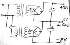
connect the other two secondary wires to your bridge rectifier and its +/- outputs are your +/- 35V rails with respect to 0V
if your target is +35v / 0v / -35v then like this:
Using this drawing can I parallel or factor in extra smoothing caps whilst maintaining your polarity example ?
Maybe inductors too ?
I think this is maybe what I was imagining all along but never had the knowledge to implement it correctly.
Thanks
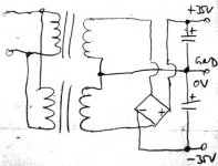
colossusfan is right, this is the alternative with just one bridge;
just have in mind, single bridge must be capable to handle power from both trafos combined.
you must have smoothing caps, at least one per rail, polarity as shown; that could be - say - 10ooo uf each or several smaller in parallel; or separate caps for both channels; xxxxxuf your choice; must be 40v min., better 63v.
inductors, do you mean chokes ? so far I know gainclones are chip amps which have pretty good PSRR (power supply rejection), so hum may not be an issue; why inductors ?
Attachments
Single brdge rectifier.... Not quite!
Quote: ok first of all you need just ONE fullwave bridge!!
Quote: colossusfan is right, this is the alternative with just one bridge
Actually, not quite true....
Whilst it will work with a single bridge rectifier under ideal conditions (equal current load on each DC rail), things can go badly wrong if the load currents become significantly unbalanced (say, a DC fuse blows).
What happens then is that both transformer secondaries effectively become half-wave rectified and their cores saturate.
What happens next will depend on the transformer construction, standard laminated ones will buzz and get hot, torroidal ones will go into hard saturation and will either blow the mains fuse or burn out.
There is a difference between having the secondaries on a common magnetic circuit and in separate ones (2 transformers). We had a long discussion on this over at EEVBlog.
The long and short of it, if you value your really nice quality transformers, then a second bridge rectifier, as in payloadde's drawing is a small price to pay to protect them from unbalanced (or one rail open) load conditions.
so you have two transformers and four secondary leads, connect two of the secondary leads together (from DIFFERENT transformers) and measure the voltage across the other two, it will be either about twice one of them or near zero
if its near zero change around the leads from one of the transformers so you get twice the voltage, once you have done that you have the correct phasing for a centre tapped winding, make sure you keep this phasing as well as the phasing of the primaries
now this secondary centre tap becomes your 0V or ground rail
connect the other two secondary wires to your bridge rectifier and its +/- outputs are your +/- 35V rails with respect to 0V
What about if you have a single 25v (secondary) transformer ... but one with 2x secondary windings?
Can you connect 2 of the 4 ends together ... and measure the voltage across the other 2?
If you measure around 50v then that shows the 2 windings are in the same polarity - and that is the way you connect them to each diode bridge. Whereas if you measure around 0v then that shows the secondaries are connected in opposite polarity?
Thanks,
Andy
It is more than just connecting 2 of the 4 ends together. You do need to connect 2 leads from different windings together or you will short a secondary.
Sure, Mark - I took that as read ... but I didn't write it well enough!
So let's assume the 25v secondaries have ends marked:
* A1 and A2
* B1 and B2.
If I connect an 'A' wire with a 'B' wire and read around 50v then that shows the 2 windings are in the same polarity - and that is the way you connect them to each diode bridge.
Whereas if I measure around 0v then that shows the secondaries are connected in opposite polarity?
Andy
If yer using chipamp.com PCBs they use the two bridges method. The output grounds are then joined only at the chip amps common ground plane. IMO lowest ripple at the expense of an extra diode drop. Otherwise take care of exactly how you wire the single bridge and not muck up grounding > route the high cap charge pulses away from your ground. do use twisted wires in pairs
Half-wave rectification of a transformer output does not cause core saturation. DC in causes saturation, not DC out.gyro said:What happens then is that both transformer secondaries effectively become half-wave rectified and their cores saturate.
Whoa there DF96, not true at all!
The transformer core doesn't care what winding causes the DC magnetization - how could it possibly know???
The generally accepted formula (for capacitive filter as shown in the drawings) is Idc = 0.28 * Iac for half wave rectifier and Idc = 0.62 for bridge rectifier. Thus a reasonable assumption that a normally loaded transformer will saturate if it is suddenly forced into half wave rectified configuration.
Remember this is for a lost load on one of the output rails, not an overload.
Aside from infinia's excellent comment about minimising ripple, the false economy of skimping a bridge rectifier could easily result in smoking the two most expensive parts in the whole unit!
Edit: And those loading figures are for a traditional EI transformer, for an effectively gapless torroidal transformer with its lower magnetisation headroom I bet it saturates much sooner than that.
Last edited:
A transformer works by ensuring that the primary and secondary currents are such that the resultant magnetic flux almost cancels. Half-wave rectify the output and you get DC in the input too, which almost exactly cancels. The transformer is not interested in which winding has DC, but it is very interested in whether that DC is balanced by another winding. Feed DC in and you get saturation. Generate DC out and the transformer will ensure that it gets balanced by the primary.
In the 1960s on a summer evening a significant proportion of the load on the local mains supply was radio and TV sets which used half-wave rectification. I don't remember hearing about local distribution transformers going up in smoke as a result.
In the 1960s on a summer evening a significant proportion of the load on the local mains supply was radio and TV sets which used half-wave rectification. I don't remember hearing about local distribution transformers going up in smoke as a result.
Sorry, but I have to disagree.
What we're interested in is the total (net) magnetising current of the core (note current). Yes, if you put a DC offset on the feed to the primary then it will magnetize the core further in one direction than the other - ok if the core has the headroom to absorb the additional flux without saturating, hence the problem with torroidals, they have a very 'closed' magnetic circuit and low saturation margin.
Exactly the same occurs with an uneven (half wave) current draw on the secondary, it unbalances the core flux in exactly the same way. Again the core must have sufficient headroom to absorb the imbalance or saturate - to be able to deliver a half-wave output it must draw a more half-wave current on the primary otherwise where does the current on the other half cycle go? - the answer...The net core magnetization shifts as before. I don't understand where you get the flux cancelling bit.
As for the AC/DC sets in the 60's (and 50's) on domestic supplies. They would have formed a very small proportion of the overall load, the vast majority of it being heating and lighting load. Even in the radio and TV sets it was only the low current HT that was rectified (and that though a high impedance selenium or valve rectifier), the series valve heater chains was wired directly across the incoming supply via a dropper resistor, the rectifier would never have coped with the heater current (and no need anyway). Hence a very low net DC imbalance for the electricity supply to absorb.
If you tried running lots of higher current half wave devices of the mains these days you'd soon have the authorities after you, there are already enough problems with humming torroidals as it is and they have more than enough on their plate with lousy AC power factor.. I can't think of a single household item that uses half wave rectification these days.
At the end of the day, the problem is there - It would be very silly to deliberately run the risk of damaging expensive parts when there is such a simple way of avoiding that risk using a comparatively cheap part that you're already buying one of anyway.
Last edited:
Sure, Mark - I took that as read ... but I didn't write it well enough!
So let's assume the 25v secondaries have ends marked:
* A1 and A2
* B1 and B2.
If I connect an 'A' wire with a 'B' wire and read around 50v then that shows the 2 windings are in the same polarity - and that is the way you connect them to each diode bridge.
Whereas if I measure around 0v then that shows the secondaries are connected in opposite polarity?
Andy
Measure the resistance to confirm A and B, if you get it wrong you may damage the transformer.
As I said, a transformer works by adjusting the currents so their fluxes almost cancel - the "flux cancelling bit" is how transformer work. Take a current from a secondary on one half-cycle only and the primary current will only flow on that half-cycle too (apart from a little magnetising current). Taking DC from a transformer is completely different from putting DC into a transformer. This may seem counter-intuitive (it took me a while to realise it).gyro said:Exactly the same occurs with an uneven (half wave) current draw on the secondary, it unbalances the core flux in exactly the same way. Again the core must have sufficient headroom to absorb the imbalance or saturate - to be able to deliver a half-wave output it must draw a more half-wave current on the primary otherwise where does the current on the other half cycle go? - the answer...The net core magnetization shifts as before. I don't understand where you get the flux cancelling bit.
I said a summer evening - very little lighting and no heating. For an AC/DC radio set the HT draw would be around 70mA and the heater 100mA. Not a low net imbalance. For a TV it might be 150-200mA HT and 300mA heater - again similar.As for the AC/DC sets in the 60's (and 50's) on domestic supplies. They would have formed a very small proportion of the overall load, the vast majority of it being heating and lighting load. Even in the radio and TV sets it was only the low current HT that was rectified (and that though a high impedance selenium or valve rectifier), the series valve heater chains was wired directly across the incoming supply via a dropper resistor, the rectifier would never have coped with the heater current (and no need anyway). Hence a very low net DC imbalance for the electricity supply to absorb.
The fact that mains sometimes has DC on it (and hence causes humming toroids) is proof that there are still half-wave supplies in some modern items. Mains DC voltage comes from the resistance of the local mains circuit creating an unbalanced voltage drop if someone is drawing DC current - so one transformer drawing the DC (quite happily) causes others to saturate because their DC is unbalanced by secondary currents.I can't think of a single household item that uses half wave rectification these days.
As I said, a transformer works by adjusting the currents so their fluxes almost cancel - the "flux cancelling bit" is how transformer work. Take a current from a secondary on one half-cycle only and the primary current will only flow on that half-cycle too (apart from a little magnetising current). Taking DC from a transformer is completely different from putting DC into a transformer. This may seem counter-intuitive (it took me a while to realise it).
Hmm, need to think about that one, as you say, not intuitive. A transformer is an AC device so it can't take current on just the half cycle (can it???) apart from magnetizing current Need to read up on that one but it doesn't sound right to me that this wouldn't cause a 'DC' magnetization of the core. As I say, no longer (quite) as sure at this stage, but it doesn't sound right
Regardless of this quandary, with, say, a 50% loaded transformer, an unintentional switch into half-wave operation would put it into overload. So something worth avoiding by using a second bridge anyway.
I said a summer evening - very little lighting and no heating. For an AC/DC radio set the HT draw would be around 70mA and the heater 100mA. Not a low net imbalance. For a TV it might be 150-200mA HT and 300mA heater - again similar.
True, you did, missed that. It would also be true to say thought that under those conditions the distribution transformer would be running very lightly loaded relative to its full winter load rating, so would probably have a fair amount of headroom available. Well within the Idc = 0.28 * Iac (+ some resistive lighting load) limit???
The fact that mains sometimes has DC on it (and hence causes humming toroids) is proof that there are still half-wave supplies in some modern items. Mains DC voltage comes from the resistance of the local mains circuit creating an unbalanced voltage drop if someone is drawing DC current - so one transformer drawing the DC (quite happily) causes others to saturate because their DC is unbalanced by secondary currents.
Yes I know, but can YOU think of one, consumer or industrial? because I can't. It doesn't make sense to actually design a product with half-wave rectified transformer because of the poor economics of needing a larger transformer and bigger cap vs the cost of a few diodes. Yes DC does occur - I have an Instek PSU with a torroid that hums suddenly at various times of day. This could be due to periods of high line I suppose but I think I have measured some DC in the past.
Yes. I realise that undermines my argument!gyro said:It would also be true to say thought that under those conditions the distribution transformer would be running very lightly loaded relative to its full winter load rating, so would probably have a fair amount of headroom available.
Adding load to a transformer does not push it into saturation. On the contrary, most power transformers are near the limit of saturation when unloaded and loading moves them away from saturation. The current limit is usually set by heating (core and copper). Very cheap transformers will sometimes saturate unloaded, but work fine with a load. I agree that accidentally going into half-wave mode will heat up a transformer, but this is not saturation.Well within the Idc = 0.28 * Iac (+ some resistive lighting load) limit???
- Status
- This old topic is closed. If you want to reopen this topic, contact a moderator using the "Report Post" button.
- Home
- Amplifiers
- Power Supplies
- Two transformers