I would like to make use of two transformers having a 230V primary, 24VCT secondary. I live in a 115VAC mains country (USA). I can get these transformers cheaply. I would like to build a chip amp power supply that has 24VAC > rectifier > filter caps > DC rails.
Can I use two of these 230V transformers, with their primaries wired in series and their secondaries wired in series? Is the connection on the secondary side, between the two transformers, like a center tap?
Below is a picture of the approach, using two transformers and two bridge rectifiers. Can I also use one bridge like one does with a center tapped transformer?
Thanks for your help on this. I am not 100% sure, and did not see other posts about this, so I thought I would put the question out there.
-Charlie
You didn't say what you are expecting in the output. However, I would think you'd connect the primaries in parallel, not series. That will give half rated output on each winding. So with 12V from each transformer you can connect them in series to get 24VCT and use a single bridge to give + and - dc with respect to the center tap.
updated schematic
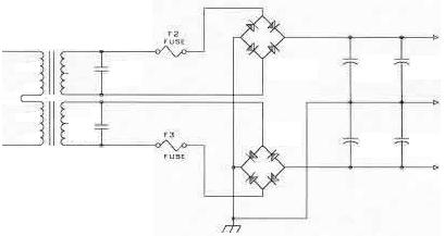
Yep, you're right. I want to connect the primaries in parallel and the secondaries in series. Here is an updated schematic:

I want to supply 115VAC to the primaries, get out 2x24VAC (24-0-24) from the secondaries, and connect the bridges and filter caps as shown. The result should be something on the order of +/- 33V DC rails.
-Charlie
Yep, you're right. I want to connect the primaries in parallel and the secondaries in series. Here is an updated schematic:
I want to supply 115VAC to the primaries, get out 2x24VAC (24-0-24) from the secondaries, and connect the bridges and filter caps as shown. The result should be something on the order of +/- 33V DC rails.
-Charlie
Im assuming alot of things.
you have 230/115 primaries. So series for usa and parallel for UK
2 24vac transfomers
So you can wire like chipamp.com
yes the positive of the lower and the negative of the upper (i know there is some growning in the backgound, shut up) transformer acts like a center tap.
you have 230/115 primaries. So series for usa and parallel for UK
2 24vac transfomers
So you can wire like chipamp.com
yes the positive of the lower and the negative of the upper (i know there is some growning in the backgound, shut up) transformer acts like a center tap.
Usually 230 V transformers are actually 2x 115 V on the primary windings.
To use them in 220-240 V countries, you connect the primary windings in series to get the rated output. That way the 230 V is divided into 2x 115 V.
This means you will get the same rated output connecting them in parallel to 110-120 V mains countries, not half! The windings still get 115 V each and therefore produce the same output voltage on the secondaries.
EDIT: you just beat me to it...
EDIT2: primaries parallel for 115 V mains, in series for 230 V... (the opposite of what nightanole wrote).
Last edited:
Nightanole and Jitter: THERE IS ONLY A SINGLE PRIMARY ON EACH TRANSFORMER. Sorry, should have made that more clear. Secondary voltage would be fine if I was in another country, but in USA if I apply 115V to the primaries I get only 12V at the secondary. I would prefer to have 24VAC output, and this is why I want to use two transformers as shown.
EDIT: I updated the schematic with some voltages. Hopefully that is more clear now.
-Charlie
EDIT: I updated the schematic with some voltages. Hopefully that is more clear now.
-Charlie
Last edited:
If the primary is a single winding you are out of luck, 12V is all the transformer will give, if they cost nothing and weight is no issue, use 4 of them, load regulation will be slightly worse than 2. I usually wire the secondaries in series with only one bridge rectifier.
240V power is usually available in the usa to run larger domestic appliances. It may be available at the fuse board but the appropriate outlets may not been installed.
If that is not an option you need either a 110/240V transformer or a 110/110V transformer to raise the voltage to around 230V . Korean stores are a good source of these step up transformers.
110/24V transformers should be readily available for little over scrap price, many machines use them for the control voltage, I find them inside US made equipment frequently. often the whole machine has a 415/120V transformer to run the original controls.
A fault in the schematic, the earth on the DC side should come from the filter capacitor not the bridge rectifiers.
Last edited:
If the primary is a single winding you are out of luck, 12V is all the transformer will give, if they cost nothing and weight is no issue, use 4 of them, load regulation will be slightly worse than 2. I usually wire the secondaries in series with only one bridge rectifier.
240V power is usually available in the usa to run larger domestic appliances. It may be available at the fuse board but the appropriate outlets may not been installed.
If that is not an option you need either a 110/240V transformer or a 110/110V transformer to raise the voltage to around 230V . Korean stores are a good source of these step up transformers.
110/24V transformers should be readily available for little over scrap price, many machines use them for the control voltage, I find them inside US made equipment frequently. often the whole machine has a 415/120V transformer to run the original controls.
A fault in the schematic, the earth on the DC side should come from the filter capacitor not the bridge rectifiers.
NOTE: There is a single primary on each transformer and the secondary is 24VCT when the primary is connected to 115VAC. Sorry for the mistake in my first post about the secondary voltage. The voltages shown in the figure below are correct:
I have to disagree about the grounding scheme. The return (labeled GND) from the power amp should be connected at the caps (a star ground) not at the bridges. The earth connection is just to establish a voltage reference, I believe, and no components are connected at that point in the circuit.
The transformer cost me $8 and is 350VA. I am not going to run a separate 230V line from my mains panel just so I can hook these up! Thanks anyway for the idea. I am set on using 115VAC input.
-Charlie
Last edited:
Yep, you're right. I want to connect the primaries in parallel and the secondaries in series. Here is an updated schematic:
I want to supply 115VAC to the primaries, get out 2x24VAC (24-0-24) from the secondaries, and connect the bridges and filter caps as shown. The result should be something on the order of +/- 33V DC rails.
-Charlie
This circuit will work fine, except that the output voltages may well be lower than you are expecting.
Assuming that each transformer is nominally rated as 230v primary, 12-0-12v secondary, with 115v on the primary the total secondary voltage (end to end, centre tap open) will be about 12v rms. After the full wave rectifier and filter capacitor, this will yield about 16v on each filter capacitor. So your DC output voltages will be (about) +16 and -16v.
If I have misunderstood your statements about the nominal primary and secondary ratings of the transformer, please correct me.
hi CharlieLaub,
I think you knew what you were doing from the start and asking the question has only confused the situation. 🙂
Ensure you follow standard standard safety practices, like a fuse on the mains, and give it a go. Make sure you get both secondaries around the right way. You usually use the dot notation to indicate the orientation of the coils.
If you have not done PSUs before, get a qualified person to supervise. When I first started doing PSUs I had a observer watching, ready to help if something went wrong.
regards
I have to disagree about the grounding scheme. The return (labeled GND) from the power amp should be connected at the caps (a star ground) not at the bridges. The earth connection is just to establish a voltage reference, I believe, and no components are connected at that point in the circuit.
-Charlie
That makes sense.
This circuit will work fine, except that the output voltages may well be lower than you are expecting.
Assuming that each transformer is nominally rated as 230v primary, 12-0-12v secondary, with 115v on the primary the total secondary voltage (end to end, centre tap open) will be about 12v rms. After the full wave rectifier and filter capacitor, this will yield about 16v on each filter capacitor. So your DC output voltages will be (about) +16 and -16v.
If I have misunderstood your statements about the nominal primary and secondary ratings of the transformer, please correct me.
EACH transformer is rated for:
230VAC input >> 48VCT output @ 7A
115VAC input >> 24VCT output @ 7A
So using two as shown should allow me to get:115VAC input >> 24VCT output @ 7A
115VAC input >> two 24VAC outputs
Sorry again for all the confusion on the voltages! 😱
-Charlie
EACH transformer is rated for:230VAC input >> 48VCT output @ 7ASo using two as shown should allow me to get:
115VAC input >> 24VCT output @ 7A
115VAC input >> two 24VAC outputsSorry again for all the confusion on the voltages! 😱
-Charlie
Thanks for the clarification.
Just so that we have got our terminology straight, I would describe this transformer as
nominal rating: 230v primary, 24-0-24v secondary, 336VA rating
This being the case, your circuit is fine and your voltage expectations (+33v, -33v) are going to be pretty close to the mark.
If you are having any difficulty analysing the proposal, think of it as two independent supplies:
An externally hosted image should be here but it was not working when we last tested it.
An externally hosted image should be here but it was not working when we last tested it.
with the GND nodes commoned. Does that make it easier?
- Status
- Not open for further replies.
- Home
- Amplifiers
- Power Supplies
- two transformer power supply wiring