Leolabs said:What is the optimum value of:
1)low frequency cut-off point,
2)DC offset trigger point
???????????
For (1) a good value may be 0.5 Hz (for protection circuit only, not for frequency response of the equipment). For (2) is customary to set the trigger point equal to a silicon diode drop in either direction.
Hi
Piercarlo
PS - However these are questions usually solved empirically, not with "formulas" or other "fixed rules".
")
A DC protection could be defined as this:
Full power at 20 Hz => the protection must not trigger at chosen DC level, 1-2 volts
Filter is chosen so the protection gets as fast as possible.
I used a 4th order Tjebusjev (can't spell it) active filter at 7 Hz and trigger level at 1.5 Volts. This was made for a 180/300 W amp.
http://sjostromaudio.com/hifi_pics/hifi_100pr/qro_pcb_top.jpg
The DC protection is at the bottom of the picture.
Hi,
I agree with Peranders logic although not his chosen values.
I would try to get the power amp to pass 10 to 15Hz at full power without triggering the DC detect. This is quite onerous and would tend to be adopted by those looking for SUB-BASS response with very wideband speakers.
The biggest problem with that first criteria is the slowness of response due to the filter needed to keep the DC detect from triggering.
Peranders choice of 4pole is unusual and certainly 7Hz is unusually high. Most would fit a 0.5Hz to 2Hz filter and use single pole at the lower frequency or two pole at a slightly higher frequency.
The second test then becomes how fast the filter and trigger operate at a 1.5V DC test signal (battery?) I would be looking for less than 1second and preferably less than 250mS.
Peranders,
could you post details of your 4pole filter (Chebyshev?) and DC detect?
I think my spelling is a simplified English translation rather than literal translation.
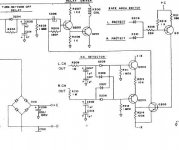
one amplifier i'm well familiar with uses an RC time constant with a corner frequency of .32 Hz in it's DC detector. it also uses a DC servo with a cutoff frequency of 5hz to keep amp offset zeroed. so the amp frequency response extends down to 5 hz, and the dc detect circuit operates at .32 hz for a frequency margin of more than 10:1. if you want to protect against medium frequency subsonics (from .5-10hz), you could always change the rc time constant.
Attachments
Hi Peranders,
Have a rethink on your comments.
is it too early on a Saturday morning?peranders said:Andrew, remember that the speed of the protection is a function of:
1 Max output power and lowest expected _normal_ frequency
2 DC level for triggering
There is no such thing as DC, more like slow AC and this is for you to detemine how slow this AC is.
Have a rethink on your comments.
- Status
- This old topic is closed. If you want to reopen this topic, contact a moderator using the "Report Post" button.
- Home
- Amplifiers
- Solid State
- Two questions about amplifier's protection circuitry