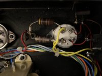
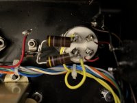
I have two Wright WPA3.5 monoblock amplifiers modified to work with 45 tubes at 180 plate amp voltage. When modifying them a wierd thing was happening. The same configuration of the same value power reducing resistors resulted in two different results on the two amplifiers. One the expected same value and one half the value. Back then I solved this problem adding another same size 4K7 resistor in series to end up with the same measurement and VDC on both amplifiers and they have worked well. Now I want to figure out why it is happening and fix the underlying cause. All four Audio Note tantalum 4K7 resistors test 4K7 when unattached. Both 80 tubes have been tested and swapped out with others. Both 80 tubes are turned the correct direction. I was careful to install both sides in the exact same configuration but I still get half the measure. I even switched the yellow heater wires and nothing changed. Does anyone have any suggestions why this is happening? I have included pictures. In the left side picture the red wire was attached when testing. Thank you for the help.
Attachments
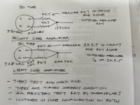

When using the two 4k7 in series the cathode current was about the same 34.5 mA. When using just one 4K7 per side on amp in question the cathode current was 52.5 mA. I assume from the resulting higher 206 VDC versus 153 VDC.
Is the cathode current the same for both?
That's the important thing.
If the drop across the resistors is different, and the resistors are the same, the currents are different. Ohms Law and all that.
Jan
That's the important thing.
If the drop across the resistors is different, and the resistors are the same, the currents are different. Ohms Law and all that.
Jan
34.5 in one and 52.5 in the other. But what could cause this to happen? Same VAC from transformers so assume they are fine. If something in the amp is pulling more current is there something connected to ground that shouldn't be. But why would that cause the resistors to measure exactly half of their value?
It may help to note that this is a directly heated rectifier, resistors on the filament/cathode.

Power off, take the tube out, and measure the resistors again.
One resistor is open (or bad joint). The '80 filament is like one Ohm. So two 4700r resistors in-circuit should read 2350.25 Ohms. Not 4700.One the expected same value and one half the value.
Power off, take the tube out, and measure the resistors again.
I did remove the 80 tube and tested the resistors again and got the same 4K7 result on both. I guess the open resistor acts like a piece of wire so when tested in or out of the loop of wire it tests at 4K7 because of the other good resistor is in the loop. Was not expecting possibility of open resistor. Will pull out and confirm if open resistor tonight. Thank you.
yes, one of the voltage reducing resistor measured OL. Of the two one looked brand new and the other one looked older and used. Of course the brand new looking one was the bad one. Thank you again!
Those look like 47R resistors in the photos, but maybe not. They also look toasted, so replace all of them with a larger wattage.
All good fortune,
Chris
All good fortune,
Chris
Hi. Resistors in the photo are 5 color , not 4 color ,so calculation should look like 4 7 0 and add one zero(last color 1) ,then tolerance percentage, so it becomes 4700 ohms .
- Home
- Amplifiers
- Tubes / Valves
- Two Pairs of Power Reducing Resistors Measuring Differently in Same Configuration