unless a kind subject of his majesty present here agrees to buy it and send it to rallyfinnen 🙂 🙂EBB150 will cost double including shipping and outrageous import taxes thanks to brexit.
The cheapest solution ever would be Maplins with Prasi's layout published here somewhere.
I built those as a sanity project during lockdown. They sound amazingly well for the simplicity.

???? After 1 Juli 2021, for orders up to a consignment value of €150 imported into the EU......hooray, N-O C-U-S-T-O-M-S!!!
''IOSS (or import One Stop Shop) — is a taxation process for the European Union. It means that buyers are charged with VAT while they make an order, and the funds are sent directly to the authorities. This makes the process of passing the customs more easy and effective, and clearer for the buyer.''
https://vat-one-stop-shop.ec.europa.eu/index_en

This has worked for me too when ordering from big players like Mouser, Amazon and I think Aliexpress, but with smaller suppliers I'm not sure. Definitely not private sellers. Fees are added up front instead of when the package arrives from outside EU, so you can see the expensive price before you buy, and not be surprised after 🙂 The Swedish krona is not worth much these days, so everything is expensive now.
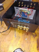
Some mechanical work has started on my thrift shop Pioneer. I recycled a heatsink from a scrapped AV receiver, and cut it in two pieces. Nothing fancy, but they should give some additional cooling compared to the tiny heatsinks that were in the amp from factory. I guess I'll have to balance heat vs bias.
Also took out the main caps, thinking they should be a bit beefier with the increased idle current, but did not find any suitable ones in my boxes of recycled crap 🙂 Maybe the standard ones will have to go back in, I think they were 8200uF. I don't want to spend too much on this build, it's more of an experiment, so far only bought the lat-fet's, and they cost about the same as I paid for the amp years ago.
There are some traces of other experiments visible too..
I meant eBay. My last shipment arrived from the USA /to Bulgaria, EU/. I received it by from the neighborhood beer garden. Oops, error..... from the neighborhood post office🙂. Additional fee 3.0 BGN /1.5 EUR/.
Order info:
- total amount US$118.71
''Sent through eBay international Shipping".
/eBay international Shipping Program
Buyer Terms & Conditions/
https://pages.ebay.com/shipping/globalshipping/buyer-tnc.html
Order info:
- sent Oct 11, 2023
- delivered on Fri, Nov 17
- net amount US$59.00
- postage US$39.57
- VAT US$19.71
- total amount US$118.71
''Sent through eBay international Shipping".
/eBay international Shipping Program
Buyer Terms & Conditions/
https://pages.ebay.com/shipping/globalshipping/buyer-tnc.html
Try making the Maplin Mosfet amp .... will sound just as good in my opinion
all the best
all the best
I did some 'cut and paste' on the PCB yesterday to switch the pinout for the latfet's. Today I mounted the outputs and tried to power it directly to the drain pins from a bench supply, but would not get more than maybe 0,5V before current limiting kicked in. I set it low, but still think the voltage should slowly go up, charging the PS caps, and possibly limit when current starts flowing in the circuit. Did some basic sanity checks, but could not find anything obvious, so I called it a night..
Not all of these old MOSfet amp concepts sound great. They measured fine at their time, but there are not many excellent ones. The Hafler was considered one of the better ones, but a if you want really perfect sound, take one of the many LM3886 chip amp PCB's. A member here does some of, or maybe, the finest implementations, but they come at a price. Even some of the better China options sound extremely good. Buy the LM3886 Chip from Mouser etc, only get the China PCB. Passive parts of these kit's usually work.
I like to "butcher" old amps, too, because of the cool looks. I found many old pre amp sections of such vintage amps to sound very transparent, while the power stage audible suck's. So the bad part has to go. I first turn them into pre-amps, then test them in A/B comparison and may install a nice power amp.
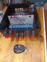
Just to give you an idea how I test, have a look at the pictures. Beeing objective is hardly possible, if you have a break between listening tests. Also your "sound memory" is extreme limited.
This device switches wireless between sources (like two CD player to one Amp or two amps to the same speaker or combinations). So I don't fool my self, just as many in HIFI do. Contrary to some loud voices, amps do not "all sound the same". Such a switching device, carefully adjusted in level, instandly shows that.
I like to "butcher" old amps, too, because of the cool looks. I found many old pre amp sections of such vintage amps to sound very transparent, while the power stage audible suck's. So the bad part has to go. I first turn them into pre-amps, then test them in A/B comparison and may install a nice power amp.
Just to give you an idea how I test, have a look at the pictures. Beeing objective is hardly possible, if you have a break between listening tests. Also your "sound memory" is extreme limited.
This device switches wireless between sources (like two CD player to one Amp or two amps to the same speaker or combinations). So I don't fool my self, just as many in HIFI do. Contrary to some loud voices, amps do not "all sound the same". Such a switching device, carefully adjusted in level, instandly shows that.
Attachments
Last edited:
I'm sorry, wrong link above. Last Updated - August 9, 2022:
https://pages.ebay.com/internationalshippingprogram/buyer/terms/
https://pages.ebay.com/internationalshippingprogram/buyer/terms/
@Turbowatch2
Thank you for the input, but I'm not interested in chip-amps at the moment. No access to the internals make it less interesting 🙂
I'm not planning to build anything from scratch at the moment, just play around a bit with the 'stash of junk' I've got. I have several assembled PCB's not built into complete amps too, I better finish those before I get more.. 🙂
I found the problem today, I had the outputs in the wrong positions for one channel (P/N switched). Now it powers up, has no DC offset, and biases as expected. However I have a small oscillation on one channel in the MHz-range (end of the range for my cheap scope). If I turn bias down to 0 it disappears.
I put my finger in different places on the PCB, and I found that putting my finger on the pins of Q308/Q10 and C326 the oscillation disappears. According to sim it should be stable as it is, but I'm missing the models for the drivers, and there is the influence of the PCB too. I tried caps between drains on the outputs and ground, but it did not seem to do anything.
One step forward at least.
I played around with this one a bit today:
-100ohm gate resistors, did not help.
-removing C346 did not help
-removing speedup cap on feedback C326 reduced oscillation amplitude a little
-touching anything in the 'inverted' side with my finger stops the oscillation (Q304, Q310, Q312)
-I tried with a small 4.7p as Miller cap in various places, but it did not do much
-mounting it in the chassis I had oscillation on both channels, and amplitude was higher on the channel that also oscillates on the bench. On the bench I have 20V rails, and in the chassis abt 40V.
-I changed the LTP transistors to (supposedly) faster ones (also lower hfe), and got 15V DC on the oscillating channel.. but no oscillation. Can't remember the type of transistors now. I had a hard time finding replacements with the same pin config in my box of transistors, most of them has the base in the middle, and many are 'recycled' so they have short legs.
To be continued..
ECX10N20 needs a 270 Ohm gate resistor
ECX10P20 needs a 150 Ohm gate resistor.
They should be close to the mosfet.
You can try this to stop oscillation
Of course there can be other issues, but ... make a try.
ECX10P20 needs a 150 Ohm gate resistor.
They should be close to the mosfet.
You can try this to stop oscillation
Of course there can be other issues, but ... make a try.
Ok, should be worth a try.
I was just thinking that it would be something else, since I did not see an improvement with the 100ohm resistors, and putting my finger in the mentioned positions kills it, but not putting my finger on the gates and in that area.
The 100ohm resistors I put in are however in the positions of R348&350, so there is some distance left to the gates. C332&334 are still mounted, so I figured it would be better to have the resistors in the original position, before the caps, forming an RC with them + the gate capacitance. I guess I could just 'lift' the gates from the PCB and put a resistor in between.
H
HAYK

I actually have not even simulated distortion, I'm just hoping to get it in working order.
This is more like a challenge to myself, to make the amp work with laterals, and hopefully with decent performance. I like analogies, so I would say it's like converting a diesel engine to petrol, and get it to start and run, not making a drag racer out of it. Maybe it will run smoother than the diesel, who knows! 😉
This is more like a challenge to myself, to make the amp work with laterals, and hopefully with decent performance. I like analogies, so I would say it's like converting a diesel engine to petrol, and get it to start and run, not making a drag racer out of it. Maybe it will run smoother than the diesel, who knows! 😉
So, I found the problem with DC. One of the old 2sc1815 transistors I (thought I) used for inputs was actually a PNP, (wrong model) so I swapped it, and DC was normal again. However, oscillation is there, and slightly worse, It even has a slight oscillation on the other channel too now.
I did not have gate resistors per recommendation, so I tried adding another 100ohm on the N FET, but oscillation was exactly the same. I doubt the main issue is there.
However, -to another discovery! From previous 'experiments' (by me) the emitter resistors on the LTP are 10ohms, not 100. When I entered this in the sim, things started looking a bit critical..
I need more resistors, so I placed an order for some in the 100-200ohms range, and also added some transistors: 2N5401 and 2SC1775. The 1775 is a straight swap with pinout, A fast one and 50mA 90V rated, so thinking LTP, but maybe can't stand the current for VAS-duty? It was a 'quick click', so I might have missed something..
Anyway, first thing to try is increasing the LTP emitter resistors when they arrive, and looks like the 1815 LTP transistors need to go too, since oscillation got worse using them. Could swap back to the originals, or the 1775's. I'm not aiming to have a super fast amp, so I might be happy adding degen (decreasing loop gain) until it's stable, if that solves it.
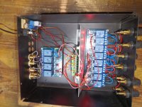
Well, it's finally 'functional'. I replaced the LTP resistors to 100ohms, and it now makes a nice looking square wave, and no signs of oscillation.
I connected it and played some music, and it sounds ok. I think I will play around a bit with the compensation etc, at least now I have a good starting point. Some distortion measurements would be interesting too.
Running a bit hot, so I might have to decrease bias, but I want to see what happens with bias vs distortion
The amp has been playing in the garage for some days now without a lid, and I was a bit hesitant about putting a lid on it with the heat it was generating.. Subjectively sounds ok, but I have better amps.. Lacking a bit in low end control, highs are possibly a bit smoother sounding than before.
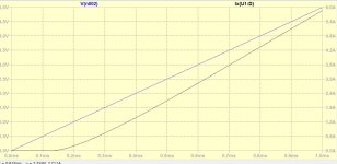
I did some measurements today and lowered the bias a bit to reduce heat while watching distortion. I have no way to measure the bias current (no source resistors), but could only measure voltages between gates. They were abt 2V before, and now abt 1.7V. Going lower the distortion started to increase rapidly.
Distortion at a few watts was abt -90dB at 8ohms, and when I switched to 4ohm (same signal) the distortion increased to almost -80dB. Only 2nd and 3rd harmonic was visible above -110dB. 2nd dominant, but 3rd not a lot lower. I ran multitone test too, and 'distortion floor' was flat around -90dB, but with decreasing the bias further, the distortion was going up in the treble.
- Home
- Amplifiers
- Solid State
- Two pairs of Lat-FETs to play with