Hi guys,
about 2 years ago as a result of my work on the new phase splitter circuit, which, as you can learn more on my website, provides up to 4 output signals, therefore I thought as a natural evolution the possibility that it could provide in making new power stages.
So I developed some schemes of which the most interesting now I make them available to the people of the forum. In particular, these two schemes seem to me that those better condense and join finally the two sides of the same coin: the CIRCLOTRON circuit and the SEPP circuit.
I ask the experts and not on the forum to evaluate them and their point of view, which might be different from mine. Even a mathematical description would be very welcome, as well as you can suggest possible ways to fruitful use .
I would add only to say that the circuits have been simulated and are functioning.
Right now I'm busy to make old projects, so I'm happy if others in the forum going to employ one of these circuits into a new project and then return here to tell about satisfaction grade. 😀
Best regards, Francesco.
Attachments
Try to search old REGENT amplifiers schematics, made in former GDR about 35 years ago, in "Vermona" factory. Nothing new, no invention...
I can not see any advantages over "normal" bridge configuration, only the complications with independent floating supplies .
I can not see any advantages over "normal" bridge configuration, only the complications with independent floating supplies .
Member
Joined 2009
Paid Member
Try to search old REGENT amplifiers schematics, made in former GDR about 35 years ago, in "Vermona" factory. Nothing new, no invention...
I can not see any advantages over "normal" bridge configuration, only the complications with independent floating supplies .
Is this on the attached schematic that you would refer to or what else?
There are more VERMONA REGENT amps.
Thanks for your comment, i did not know this manifacturer.
Attachments
Hi,
There is no ground reference. Is this a split load arrangement or is half of the semiconductors arranged as common emitter and the other half as common collector ?
Then - the term SEPP was made popular in the tube era when there was no PNP equivalent and one had to make clever arrangements to get a "complementary tube". SEPP should be avoided because it doesn't really refer to any certain design. I saw SRPP power stages, I saw white cathode followers, etc.. named SEPP.
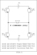
Moving on to Fig. 1
Either one pair of transistors or one PSU is too much. Considering they're all equal (hfe, S, ri) then the first arrangement (Q1+Q2) is just a heat generator since the difference in current from both PSUs doesn't change. The second is just a parallel push pull amplifier (known as circlotron) with a added useless pair of transistors. The third one is the same as the first one. No change in load current. But this could be converted to a proper full bridge arrangement (one big PSU, not two) very easily.
I don't want to disappoint you, but keep focusing on proper existing designs. The transistor is "too" easy that one could design a completely revolutionary new & perfect design from scratch. This is not a Higgs Boson 🙂
Regards, Simon
There is no ground reference. Is this a split load arrangement or is half of the semiconductors arranged as common emitter and the other half as common collector ?
Then - the term SEPP was made popular in the tube era when there was no PNP equivalent and one had to make clever arrangements to get a "complementary tube". SEPP should be avoided because it doesn't really refer to any certain design. I saw SRPP power stages, I saw white cathode followers, etc.. named SEPP.
Moving on to Fig. 1
Either one pair of transistors or one PSU is too much. Considering they're all equal (hfe, S, ri) then the first arrangement (Q1+Q2) is just a heat generator since the difference in current from both PSUs doesn't change. The second is just a parallel push pull amplifier (known as circlotron) with a added useless pair of transistors. The third one is the same as the first one. No change in load current. But this could be converted to a proper full bridge arrangement (one big PSU, not two) very easily.
I don't want to disappoint you, but keep focusing on proper existing designs. The transistor is "too" easy that one could design a completely revolutionary new & perfect design from scratch. This is not a Higgs Boson 🙂
Regards, Simon
BV.
can you post a VERMONA schematic that is similar to one of my circuits?
I'm awaiting for that.
What I attached in post 6 is a simple circlotron, otherwise what you said has no value, I'm sorry.
can you post a VERMONA schematic that is similar to one of my circuits?
I'm awaiting for that.
What I attached in post 6 is a simple circlotron, otherwise what you said has no value, I'm sorry.
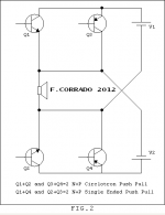
The Vermona schematic you posted is exactly the same topology as your FIG.2. Two power transistors (paralleled NPN and PNP in your schematic do the same as one transitor..) and two floating PSU. You can not see it?
FIG. 1 can not work properly as is , only if two transistors always stays off, so they are unnecessary,
FIG. 1 can not work properly as is , only if two transistors always stays off, so they are unnecessary,
and result is FIG.2.with a added useless pair of transistors.
What kind of complications with independent floating supplies do you mean?I can not see any advantages over "normal" bridge configuration, only the complications with independent floating supplies .
Please, can you write more.
Thanks
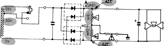
And what kind of advantage do you see?😱 For stereo amplifier you need four independent, floating PSU...It is much simpler and effective to configure it as full bridge, if this (big power) is really needed. I see this topology as relict from early times, when power transistors was very expensive, and with Uce more than 50V obsolete..So it was inevitable to do it so. But nowadays, it has no sense.What kind of complications with independent floating supplies do you mean?
I mean this floating PSU for classic bridge amplifier...
Attachments
Last edited:
Is this on the attached schematic that you would refer to or what else?
There are more VERMONA REGENT amps.
Thanks for your comment, i did not know this manifacturer.
This is actually a so called "circlotrone".
Yamaha also used this kind of OPS topology (YAMAHA)
The Yamaha picture shows problems of conventional PSU and advantages of floating PSU with bridge amplifier.
They compare unbalanced input with balanced one, fully floating, referenced to "nothing?" it is a bit strange, no? Put balanced input in "normal" amp, then it is the same "advantage", this is independent to output topology. But in the "circlotron" here are two NFB paths, more complication with compensation, both sides of output are "live", two paths to enter interference in feedback loop .. Power transistors are exposed to the same voltage, so really no advantage, just opposite. Or maybe just I can not see it, try to show me what you see as advantage?
I see only one advantage of a conventional bridge amplifier.
Current flows both power lines. These two lines can be twisted.
Current does not flow only one power line (through the loads to the ground as in a standard amplifier).
Current flows both power lines. These two lines can be twisted.
Current does not flow only one power line (through the loads to the ground as in a standard amplifier).
- Status
- Not open for further replies.
- Home
- Amplifiers
- Solid State
- Two new output stages. Have you seen before?