Two newby questions from someone who uses breadboarding instead of Spice... I'm breadboarding the 807 schematic on this page and have two unrelated but general questions.
DIY Audio Projects Forum • SE ATS25/807 two stage amp
Why is the volume control in the middle instead of at the input? Is it all the same sound wise for this circuit?
Would there be any sonic advantage of using a CCS anywhere in this simple amp? If so, on the cathode or plate?
DIY Audio Projects Forum • SE ATS25/807 two stage amp
Why is the volume control in the middle instead of at the input? Is it all the same sound wise for this circuit?
Would there be any sonic advantage of using a CCS anywhere in this simple amp? If so, on the cathode or plate?
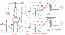
Schematic?
The volume control is not at the input to counter the effect of a possibly noisy front end ? ... who can tell without the schematic.
CCS is a waste of effort on an amplifier using valves. We do not want constant current as valves do not perform well under those conditions. A fixed bias is a different matter for the output stage as it allows for that extra voltage, wasted on cathode resistors, to be used in full.
You talking about this schematic?

If so, I would have done a few things differently. install 100k resistors, rather than a pot at the 807 grids. If you want a volume control, , 10k volume pot up at the input, feeding something around .1uF ~220nF input capacitor, 100k rather than 500k grid leaks on the 6SN7. For SE especially a cap up front is a good idea, and always a good idea before the grid of a tube to prevent noise from grid current.
Add grid stoppers to the 6SN7. 470R would be fine.
Go smaller on the screen resistors. 100-220R should be fine.
If you want to put a CCS anywhere in the circuit, replace the 27k plate resistors on the 6SN7 with something like a 10M45S CCS or a DN2450 cascode. this will allow the triode to make a bit more gain, and increase linearity a little bit. I'm not sure it would be a big difference here.
I would personally add some global negative feedback, as the damping factor is likely not the best as is- UL and pentode/tetrode output stages tend to have higher output impedance than triode mode. You would need to add a feedback resistor from the transformer secondary, and add an additional cathode resistor underneath the cathode resistor and capacitor of the 6SN7, tying the feedback resistor to the where the above components originally went to ground. Only caveat to doing this is that it will reduce gain, which may or may not work for you depending on how high your usual source signal is. I don't much care for UL on its own, and like some feedback. Others disagree.
Attachments
Last edited:
Keep in mind it wont be very powerful, 3-4 watts, maybe more with higher voltage. The 807 is a great tube, and really shines at higher voltages. If all you intend to run is ~300 volts or so you may as well go for a 6L6G or 6P3S.
Keep in mind it wont be very powerful, 3-4 watts, maybe more with higher voltage. The 807 is a great tube, and really shines at higher voltages. If all you intend to run is ~300 volts or so you may as well go for a 6L6G or 6P3S.
Not a problem. I'm progressing along with headphone amp experiments of all kinds, listening to a lot of different simple circuits and tubes, learning. Trying to breadboard one a week if I can find the time!
Switched headphones or a small pair of nearfield speakers is the eventual usage, for a computer desk. I have a small 8 inch powered sub hooked off the speakers so I dont need the watts. This is the first UL tetrode I'm trying.
I invested considerable time making a very work-efficient magnetic-base bread boarding system with modular voltmeters, sockets, jacks, ground bus, etc. I'll have to post on that soon. I can tear down a circuit like this and build another one with the same part count in an hour and the parts dont flop over. I can have 10 voltmeters at once, kind of like Spice with real parts!
GNFB won't be appropriate with a PPIMV.
Also worthwhile taking care with 807 transmitters - so suggest soldering grid and screen stoppers directly to 807 socket and with minimal resistor lead length - not something that is easy to simulate ;-)
Preferably ground each speaker output winding.
Also worthwhile taking care with 807 transmitters - so suggest soldering grid and screen stoppers directly to 807 socket and with minimal resistor lead length - not something that is easy to simulate ;-)
Preferably ground each speaker output winding.
You talking about this schematic?

Thanks I put it together and it works, now I want to up the 807 voltage more to what it was designed for... and change the operating point which I assume changes the 200 ohm cathode ground, which I won't do on the fly. I'll have to sit down with the books on load lines and learn that basic activity which for most here is very basic but not for me yet. Nothing is oscillating on the scope, added 6SN7 grid stoppers. And I should ground one side of each OPT but I should make sure I'm grounding the same phase on each channel in the final stereo version. I'll do that with a sine wave just to verify polarities. On the breadboard I have no volume control, but for a computer desk amp I'm not sure I'll ever even install a volume pot at all because the computer can do that digitally. Then I have to figure out the speaker/phones switching and maybe a load resistor when it's using phones. The phones are 300 ohm.
GNFB won't be appropriate with a PPIMV.
Also worthwhile taking care with 807 transmitters - so suggest soldering grid and screen stoppers directly to 807 socket and with minimal resistor lead length - not something that is easy to simulate ;-)
Preferably ground each speaker output winding.
I'm not liking the sound here after listening longer and from what I can remember from the previous two circuits I've breadboarded, as I try one after another. I think maybe these do need NFB I don't know they just sound harsh after a while. I'll revisit the 807 later. This is the third SE flea watt amp I've experimented with that can drive near field speakers or headphones for a computer desk.
Definitely ground the negative lead of the output transformer.
How much voltage do you have to work with? This circuit will really shine at 375~400 volts 🙂
Try triode connecting them, might be more to your taste? I'm not the biggest fan of UL, but in some instances it works well enough (like the EL84, or in push pull) but I rather run pentode most of the time. Or, you could try some global feedback, although I think the gain may be too low, unless your source has a pretty hot output signal. I would try triode first, since it's a simpler change. If that's to your liking leave it as is?
Triode will give less power but will sound great in most instances.
PPIMV? "Post Phase Inverter Master Volume", I assume based on past reading? If so, this isn't push pull, so no phase inverter. I would still move the pot up front. It's a much better spot for it.
How much voltage do you have to work with? This circuit will really shine at 375~400 volts 🙂
Try triode connecting them, might be more to your taste? I'm not the biggest fan of UL, but in some instances it works well enough (like the EL84, or in push pull) but I rather run pentode most of the time. Or, you could try some global feedback, although I think the gain may be too low, unless your source has a pretty hot output signal. I would try triode first, since it's a simpler change. If that's to your liking leave it as is?
Triode will give less power but will sound great in most instances.
GNFB won't be appropriate with a PPIMV.
PPIMV? "Post Phase Inverter Master Volume", I assume based on past reading? If so, this isn't push pull, so no phase inverter. I would still move the pot up front. It's a much better spot for it.
Last edited:
Definitely ground the negative lead of the output transformer.
How much voltage do you have to work with? This circuit will really shine at 375~400 volts 🙂
Triode will give less power but will sound great in most instances.
t.
Thanks I'm going to leave it on the board until after the holiday it's worth tweaking the voltage.
- Home
- Amplifiers
- Tubes / Valves
- Two General questions about this simple 807 amp