I am building a preamp with a separate power supply chassis. I searched for threads discussing this topic, but didn't find one that was a good match to what I am planning.
My power supply chassis will have a custom transformer to drive four dual-rail supplies (filtered, but not regulated) for analog circuits and one single-rail regulated supply for digital circuits. The IEC ground will be connected to the chassis ground. I am currently planning a 14 conductor umbilical so all supplies will have their own ground connection, so all these supplies will be floating with respect to chassis ground and to each other.
The preamp chassis will use four dual-channel UltraBib regulators - two for each channel (one supplying +/- 17v for Salas DCG3 amps, and one supplying +/- 10v for op-amp circuits).
I'm assuming I want to have a single star grounding point in the preamp chassis to provide a common grounding point for each of these separate circuits. Do I need to somehow connect the preamp chassis ground to the PS chassis ground? If so, I assume I will need a 15th conductor in my umbilical and connect through a ground-break circuit, but I'd rather avoid this unless it's really necessary since I'd have to use a bigger umbilical connector.
Thanks.
I'm grappling with a similar question only I figured on creating two (stereo) +/- feeds from four secondaries. To connect signal ground back to the PSU safety ground I came to the same conclusion you did: I'd need extra ground conductors.
Perhaps this will help?
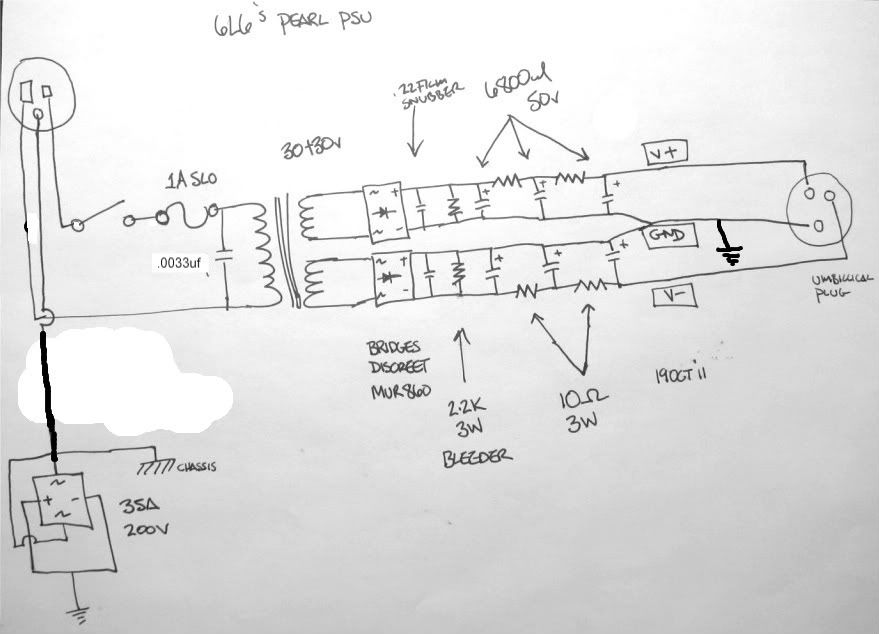
Building a Pearl 2
Perhaps this will help?
Building a Pearl 2
Thanks for the reply and link. I want to keep the grounds for the separate supplies all isolated until they are connected to a common ground point in the main chassis to avoid a ground loop, so it seems like the safest approach is to add an additional connection in my umbilical that takes the star ground point back to the power supply chassis and connects to the PS chassis through a ground break.
In his Pearl 1 project Wayne chose to connect the signal and power ground planes together on the board. Just sayin'
Earth ground the chassis of your power supply and preamp, but leave the transformer's outputs floating until they get to your preamp's power supply. The transformer secondary coils have no need to connect to anything except the inputs of your bridge rectifiers.
Since you have five separate secondary coils, you don't need to do a center-tapped bridge configuration, and there is no need to connect the coils to star-ground at all. Just use 5 bridge rectifiers, and connect their outputs straight to the filter caps. Then go to star-ground.
Since you have five separate secondary coils, you don't need to do a center-tapped bridge configuration, and there is no need to connect the coils to star-ground at all. Just use 5 bridge rectifiers, and connect their outputs straight to the filter caps. Then go to star-ground.
This is spot-on.
**EDIT Spot-on only in respect to how the bridges and caps are configured. DO NOT float your earth ground with a ground loop breaker as shown in this thread. Always connect earth ground DIRECTLY to the chassis, on it's own bolt with a lock-washer.
Last edited:
Yeah, that's what I'm thinking, with the star ground in the preamp chassis. The question I wrestling with is whether this star ground needs to be connected back to the power supply chassis through a ground break.
The preamp chassis will have a ground reference from connections to input devices and amps, so perhaps this is all that is needed.
The preamp chassis will have a ground reference from connections to input devices and amps, so perhaps this is all that is needed.
Nope, you'll just form a loop that way, from the preamp chassis, through this wire, out the chassis ground and back to the preamp through it's chassis ground.
I'm not sure if I'm missing something with the Pearl 2 reference. It looks like he is connecting the power supply ground to the chassis through a ground break, but otherwise passing it to the second chassis where it provides a reference.
In my case, should I connect all the power supply grounds together in the power supply chassis and just run a single ground connection to the preamp chassis? I was thinking it would make sense to keep them separate and only connect them at a common point in the preamp chassis.
In my case, should I connect all the power supply grounds together in the power supply chassis and just run a single ground connection to the preamp chassis? I was thinking it would make sense to keep them separate and only connect them at a common point in the preamp chassis.
It might not actually show up as noise in the system, but it's currents that don't need to be flowing at all.
Chris, I'm confused. Can you explain the loop again. I'm not sure where the ground currents would form a loop?
Whoa! Oops. No don't do it that way!
I was only referring to the way the power supply caps and bridges are hooked up.
Absolutely never float your chassis ground that way. That's the wrong way to use an earth loop breaker. Check Rod Elliot's article.
Earthing (Grounding) Your Hi-Fi - Tricks and Techniques
I was only referring to the way the power supply caps and bridges are hooked up.
Absolutely never float your chassis ground that way. That's the wrong way to use an earth loop breaker. Check Rod Elliot's article.
Earthing (Grounding) Your Hi-Fi - Tricks and Techniques
Further down in the thread, where it says "Fig 7 Example power supply" is better, but I would add a 47R metal oxide and .1uF poly cap in parallel across that bridge rectifier being used as a diode clamp. The chassis needs to be coupled to signal ground at some point, and only one point.
@Chris
WRT Wayne's Pearl 2 Figure 7...
The chassis is clearly shown attached directly to earth and Wayne states in the construction notes that,
"the chassis is directly (and with heavy wire) attached to the earth ground of the AC line".
WRT Wayne's Pearl 2 Figure 7...
The chassis is clearly shown attached directly to earth and Wayne states in the construction notes that,
"the chassis is directly (and with heavy wire) attached to the earth ground of the AC line".
Sorry, not meant to be a dig on Wayne, it's just that the first diagram is incorrect. I presume it was corrected later on in the thread, but it's like 108 pages long.
Or I am mis-interpreting his drawing. It would be correct if there were a connecting dot where the drawn-in black line connects to the diode-shunt bridge.
Sorry, I don't understand. Wrong how?
You said it doesn't have the chassis connected directly to earth and to my eyes Wayne's drawing shows exactly that.
I know the thread is long but a link to a correct circuit would be helpful so that I can rationalize what I see with what you say.
You said it doesn't have the chassis connected directly to earth and to my eyes Wayne's drawing shows exactly that.
I know the thread is long but a link to a correct circuit would be helpful so that I can rationalize what I see with what you say.
Further down in the thread, where it says "Fig 7 Example power supply" is better, but I would add a 47R metal oxide and .1uF poly cap in parallel across that bridge rectifier being used as a diode clamp. The chassis needs to be coupled to signal ground at some point, and only one point.
And actually now looking at his project, that is not needed because his power supply box only contains the power supply and not the preamp itself. Your preamp chassis will need to connect to signal ground at some point.
- Home
- Source & Line
- Analog Line Level
- Two chassis preamp grounding