Personally I´d use one bridge rectifier, one large main filter bank, separate DC going to each power amp with diodes and add extra capacitance after each.
Best of both Worlds and conceptually simplest.
Plus we deal with already rectified and filtered DC, not raw rectified AC and inherent charging pulses.
That said, any modern well designed amplifier will have gobs of PSRR so no REAL need for all this added complexity.
Best of both Worlds and conceptually simplest.
Plus we deal with already rectified and filtered DC, not raw rectified AC and inherent charging pulses.
That said, any modern well designed amplifier will have gobs of PSRR so no REAL need for all this added complexity.
Interesting idea. Try building it in LTSpice and see what isolation you get between channels.
2 transformers would be more ideal, as that would avoid any coupling within them. The only link then is the reasonably low impedance mains supply.
After playing with a network analyzer on an inexpensive valve amp, and realizing the power rails were causing (about -30 dB) crosstalk, I tried the following.
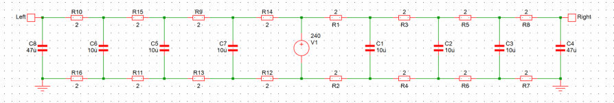
Single rectifier connected to a capacitor, which then fanned out to each channel through resistors on both the feed and return paths. Each channel obviously had its own capacitor. This worked, but not well enough. So a ladder filter was made, by adding capacitors and resistors. See the attached schematic for an example. Imagine the voltage source is the bridge rectifier.
It was a few years ago, so can't remember the number of stages (was as many as would fit) or the component values. Worked well though with a huge reduction in high-frequency coupling and reasonable improvement at the low end. There is a voltage drop due to the resistors, but small as they're low value. The idea is to have a very high-order filter to get rid of high-frequency coupling.
I find resistance in the gound between a rectifier and chassis ground a useful way of discouraging a little noise also. Somewhat unconventional in audio, but soft ground connections are fairly normal in industrial systems.
I'd not thought of using separate rectifiers. That probably would help here enormously.
2 transformers would be more ideal, as that would avoid any coupling within them. The only link then is the reasonably low impedance mains supply.
After playing with a network analyzer on an inexpensive valve amp, and realizing the power rails were causing (about -30 dB) crosstalk, I tried the following.
Single rectifier connected to a capacitor, which then fanned out to each channel through resistors on both the feed and return paths. Each channel obviously had its own capacitor. This worked, but not well enough. So a ladder filter was made, by adding capacitors and resistors. See the attached schematic for an example. Imagine the voltage source is the bridge rectifier.
It was a few years ago, so can't remember the number of stages (was as many as would fit) or the component values. Worked well though with a huge reduction in high-frequency coupling and reasonable improvement at the low end. There is a voltage drop due to the resistors, but small as they're low value. The idea is to have a very high-order filter to get rid of high-frequency coupling.
I find resistance in the gound between a rectifier and chassis ground a useful way of discouraging a little noise also. Somewhat unconventional in audio, but soft ground connections are fairly normal in industrial systems.
I'd not thought of using separate rectifiers. That probably would help here enormously.
Attachments
Enlightening indeed.try it and find out.......
Your schematic shows a circuit, that generates a bipolar supply from two secondaries using two rectifiers. In this configuration the 2nd rectifier does not make sense to me, it only roughly doubles the rectifiers losses, because app. 4 Volts of diode drops are lost, instead of two.
I thought about generating two bipolar supplies from one tapped secondary (refer to attachment in #15). By using a separate rectifier/capacitor combination for L and R, the ripple generated by loading one channel would not directly be seen by the other channel.
Anyway if it does not work well, it could easily be rewired to a shared bipolar supply with 2x20mF (and omitting the 2nd rectifier).
Of course two transformers would be the classic solution. My assumption was, that a 500VA transformer is a relatively stiff AC source, so sharing the secondary might be an option. The idea is, that the ripple from one channel is not seen by the other channel. If e.g. the left channel is heavily loaded, then the recharging duty cycle of it's rectifier is longer. A lighter loaded R channel shows a short recharging pulse which overlaps with that of the L channel. Therefore the R channel sees only the slightly reduced peak voltage, due to the voltage drop on the output impedance caused by the simultaneous charging pulse of the left channel. If a shared supply with 4 capacitors is used, the voltage drop on the output impedance would stay the same, but L and R channel would now see the half droop (because of the doubled capacitance). So the ripple for the L channel would be halved, but that for R channel would be higher.Interesting idea. Try building it in LTSpice and see what isolation you get between channels.
2 transformers would be more ideal, as that would avoid any coupling within them. The only link then is the reasonably low impedance mains supply.
After playing with a network analyzer on an inexpensive valve amp, and realizing the power rails were causing (about -30 dB) crosstalk, I tried the following.
Single rectifier connected to a capacitor, which then fanned out to each channel through resistors on both the feed and return paths. Each channel obviously had its own capacitor. This worked, but not well enough. So a ladder filter was made, by adding capacitors and resistors. See the attached schematic for an example. Imagine the voltage source is the bridge rectifier.
It was a few years ago, so can't remember the number of stages (was as many as would fit) or the component values. Worked well though with a huge reduction in high-frequency coupling and reasonable improvement at the low end. There is a voltage drop due to the resistors, but small as they're low value. The idea is to have a very high-order filter to get rid of high-frequency coupling.
I find resistance in the gound between a rectifier and chassis ground a useful way of discouraging a little noise also. Somewhat unconventional in audio, but soft ground connections are fairly normal in industrial systems.
I'd not thought of using separate rectifiers. That probably would help here enormously.
I will try to simulate it, during the next days, to make my idea more clear.
That makes sense. More capacitance and filtering is more good as long as it fits in the case and doesn't blow the fuse when filling up. Diodes being part of the filter seems good also.
My present solution is tri-amped speakers with active crossovers. The channels are driven from separate mains sockets. Bit of a work in progress but isolation is pretty good.
My present solution is tri-amped speakers with active crossovers. The channels are driven from separate mains sockets. Bit of a work in progress but isolation is pretty good.
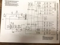
The later Adcom GFA-5200 is also connected this way (as in post #15) to make separate L and R output stage V rails from a single center-tapped secondary.
In the 5200, the front end gets separate PS rails also, but here 10 ohm resistors are inserted between the secondary and the diodes.
Could this arrangement be improved upon?
In the 5200, the front end gets separate PS rails also, but here 10 ohm resistors are inserted between the secondary and the diodes.
Could this arrangement be improved upon?
Attachments

The schematic in post #4 is exactly the power supply recommended by Rod Elliot:
https://sound-au.com/project04.htm
Rod Elliot is generally known as someone who knows what he's doing.
https://sound-au.com/project04.htm
Rod Elliot is generally known as someone who knows what he's doing.

- Home
- Amplifiers
- Power Supplies
- Two bridge rectifiers