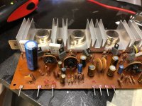
I’m changing the capacitors on my receiver and I found two big capacitors on the power amplifier board. They both have four pins and when I look at the back of the board I found that oly one looks like a dummy. Hi Can’t find Anything the Web that looks like that. Somme People talk about 3 pincapacitor that are in fact two capacitors in one with a common negative pin. Is there someone familiar with that kind of capacitor that could help me?
Attachments
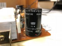

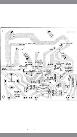
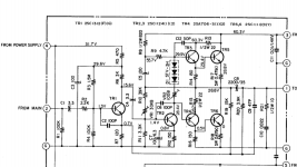
As both label, schematic an PCB layout show, you have a single 2200uF x 35V capacitor.
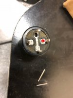
4 pins?
One of them is positive, other 3 are negative and most probably connected to aluminum case (they *might* float though).
Check for continuity between them.
Why 4?
For mounting and stability.
4 pins?
One of them is positive, other 3 are negative and most probably connected to aluminum case (they *might* float though).
Check for continuity between them.
Why 4?
For mounting and stability.
Two of those pins will be common to one of the terminals. A continuity tester should do to determine which pins are which. You can then simply solder a link wire to make the connection on a regular 2-pin capacitor
Probably not helpful but:
Nippon Chemi-Con Corporation / Aluminum Electrolytic Capacitors
The site says replacement series for EW typ is SME.
but it lists it as a :"SCREW-MOUNT TERMINAL REPLACEMENTS"
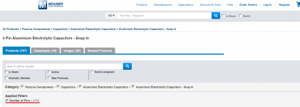
Then it lists the SME as a "SNAP-IN REPLACEMENTS" and the replacements are SMH / SMM series...Which do not have the same 4 pin pattern as yours.
Nippon Chemi-Con Corporation / Aluminum Electrolytic Capacitors
The site says replacement series for EW typ is SME.
but it lists it as a :"SCREW-MOUNT TERMINAL REPLACEMENTS"
Then it lists the SME as a "SNAP-IN REPLACEMENTS" and the replacements are SMH / SMM series...Which do not have the same 4 pin pattern as yours.
Hi,
If you look at the third picrture inside the capacitor drawing showed in the middle the four connections of the capacitor. The top it is the positive, the bottom it is floating or doing nothing and the middle ones are the ground. Hope it may help
If you look at the third picrture inside the capacitor drawing showed in the middle the four connections of the capacitor. The top it is the positive, the bottom it is floating or doing nothing and the middle ones are the ground. Hope it may help
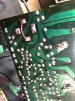
Thanks to everyone! It was more obvious what it was once remove from the board. Here are some picture of the work done.
Attachments

Also soldermask, the green stuff on PCB, is usually made of epoxy, I would of put a small piece of polyethylene (shopping bag) or PET (plastic bottle) under bare wire or use isolated one.
- Status
- Not open for further replies.
- Home
- Amplifiers
- Solid State
- Two 4 pin capacitor on the power amp PC board of my receiver