I am curious as to what is "good practice" regarding twisting the HV leads from the output of the power transformer to the tube rectifier. It seems to me that the centertap wire ought to be twisted in with the two HV wires. Any other thoughts on this one?
Joel
Joel
In addition to looks, you do it for the same reason you twist the AC filament wires to help reduce hum transmission.
For 3 wires braiding may be better than twisting but yes, the center tap should be twisted/braided with the others.
The reason for twisting the transformer wires is, as has been pointed out, to reduce mains-frequency hum radiated from those wires.
Current flowing through a wire creates an electromagnetic field around the wire. AC currents create a time-varying field around the wire that can radiate into nearby circuitry.
James Clerk Maxwell put this all together back in 1862 when he demonstrated the relationship between a handful of equations (figured out by some other pretty smart guys: Ampere, Gauss, and Faraday) which are today collectively known as "Maxwell's Equations". (He also got a unit named after him, but that's another story)
If you have equal currents flowing through two wires in different directions, and you twist the wires together tightly, then the fields will mostly cancel and radiated energy is thus greatly reduced.
Note: it is not the twisting itself that cancels the fields. It is getting the wires close together that cancels the fields. Thus twisting the wires tightly together is what we are trying to do to cancel the field.
In AC filaments, this is easy to visualize - current flows through the filament in alternating directions during each cycle. Equal (and opposite) currents flow in the filament wires during the entire cycle. Just twist them together and you achieve pretty good cancellation of the radiated field.
The full-wave power supply (two diodes, CT power transformer) is a little less obvious. Current flow alternates from one-half of the transformer HV during each AC cycle. Current flows out of the transformer on one HV side during the first half of the cycle, and out of the other HV side during the second half of the cycle.
Voltage is present at both HV transformer outputs, but the rectifier diodes prevent current from flowing through 1/2 of each transformer HV winding during the half-cycle when the rectifier is reverse biased. No current, no field, no radiation.
Current flows back into the transformer through the CT through the entire AC cycle - this is the common current "return path" back into the transformer.
Twisting just the two HV wires alone will not cancel any fields because the AC current 1) always flows in the same direction (i.e. - out of the transformer), and more importantly 2) the current only flows in alternating wires on each half of the cycle.
So yeah, in short (too late...) you should twist the HV and CT wires together to get the field cancellation effect. 😎
Sam
BTW - As a practical matter, the fields from the filament are a much bigger problem because the heater currents are much higher than typical HV supply currents. Heaters can take 300mA or more each, and you usually have multiple tubes so you can be pulling several Amps of filament current in a typical amplifier.
The field strength is proportional to current - the higher the current, the greater the field strength in a wire and thus the greater possibility of radiating hum into the amplifier.
HV supplies, OTOH, are typically in the 150-300mA range unless you get into the BIG amps. Further, the HV AC wires are not terribly long (if the amplifier layout is done correctly, with the rectifier near the HV transformer). Short wires, low current for HV means that HV AC radiation isn't as big a problem.
Filament wires route to every tube in the amplifier - which is why we spend so much time worrying about the filament supply (twisting and routing wires carefully) and you find much less information on treating HV wires in the same manner. 😎
Not quite true. The main effect is, as you say, keeping the forward and return currents close together so as to minimise the loop area. There is also a useful secondary effect in that if nearby parts of the wire have reverse orientation then the magnetic field is reversed so at distances away which are commensurate with the twist length (or further) then the fields tend to cancel. This is why AC heater wiring should always have a tight twist.rfengineer2013 said:Note: it is not the twisting itself that cancels the fields.
No. Current only flows into the CT when the rectifiers are switched on. Otherwise, twisting would not work!Current flows back into the transformer through the CT through the entire AC cycle
High voltage wires carry less current than AC heaters, but they have sharp pulses instead of smooth AC. Induction depends on rate of change of current so can still be problem.
Thanks everyone for your thoughtful replies. In Morgan Jones Building Tube Amplifiers he mentioned twisting the HV leads, but I did not see any mention of the CT. My thinking was that due to the rectifier, the two HV leads do not act as the supply and return, so I would need the CT to get the cancellation. Sam, thanks for confirming this. Very helpful!
Joel
Joel
As DF96 says, it's a matter of loop area. Follow the current from one end of the transformer winding through the diode(s), the reservoir cap, and back to the transformer. The area of that loop needs to be minimized.
Inductance is proportional to the loop area. Hence, inductive coupling can be reduced by minimizing the loop area.
~Tom
Inductance is proportional to the loop area. Hence, inductive coupling can be reduced by minimizing the loop area.
~Tom
Thank you for pointing out some of the 2ndary effects, DF. There are other good points as well, covered in the sticky on filament wiring (" The Good, The Bad, and The Ugly).
The main point of it all is that the CT is the return path for the HV transformer current, and thus the CT needs to be twisted together with the HV leads to obtain the benefits of such twisting - twisting only the HV leads provides no cancellation of the field.
I am happy the OP managed to wade through my excessively long post and understood the rationale behind the "why".
When I build my power supplies I usually take the center tap and shorten the wire just long enough to make it to my star ground which is usually right next to or attached to the PT (one of the bolts on the PT usually). The rectifier is always a little further from that point (but not much) with C1 very close to the star ground point and my ground return from C1 to the star point (very short). Filament wires I tuck into corners and 90 degree them to the sockets. Anytime I've got to cross any other wires with filament wires they are at 90 degrees. Also I think that lead dress at the sockets of the driver and output tubes is just as critical as the twisting of filament/hv to the rectifier (lead dress doesn't stop at the rectifier you must follow all the way thru all circuits).
To the point OP: I don't usually twist the CT in with the filament/HT wires as the lead is so short anyways and the PT also has a magnetic field around it (same vicinity with same ill effect). When mounting my driver tubes and output tubes I put them as far away from the star ground/filament/rectifier as I can on the chassis, and of course paying close attention to how/where the filament wires are in relation to all other wires in the circuit.
The way I explain this is not science but real world working experience. I've got dead quiet amps no hum what so ever... not even a whisper of hum.
Lead dress to me is THE art of tube amp building. Every time I build a new amp I'm obsessing on it, even more so, or at least as much as parts selection. In the end tho, safety is the most important thing with tube amp building. I obsess on that even more that lead dress, I'm still here.. knock knock.
I read Morgan Jones book on building tube amps a few times before I built one. It's a good read and I think a must read for anyone getting into this sort of thing.
Cheers,
Bob
This is the classic mistake which everyone seems to make.bobrown14 said:When I build my power supplies I usually take the center tap and shorten the wire just long enough to make it to my star ground which is usually right next to or attached to the PT (one of the bolts on the PT usually). The rectifier is always a little further from that point (but not much) with C1 very close to the star ground point and my ground return from C1 to the star point (very short).
Never include the star ground in the charging pulse loop!
Instead, CT should connect to C1 -ve terminal, then run a wire from C1 -ve to C2 -ve (if present) then from there to the star ground.
This is the classic mistake which everyone seems to make.
Never include the star ground in the charging pulse loop!
Instead, CT should connect to C1 -ve terminal, then run a wire from C1 -ve to C2 -ve (if present) then from there to the star ground.
I just looked at the last amp I built and you're right. I wired the CT not direct to star ground but to a wire terminal (right beside the star ground tho), CT to terminal strip then on to C1 and another connection from where my CT connects to star ground. are you saying I should take the negative from C1 directly back to star ground instead?? Not my schematic but this is what I follow basically without the standby and 5AR4 instead of 5U4. Is this the proper way to do it?
Cheers,
Bob
Attachments
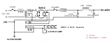
No. In that circuit the star ground should connect to the -ve end of the 100uF.Is this the proper way to do it?
Your description does not match that circuit.
The ground connections should be CT===C1-===C2-===star.
You may find older amps and radios ground the CT near the transformer but they just assumed in the 1950s that some hum was unavoidable. It is unavoidable with such wiring! Sadly, many circuit diagrams still show this wrong method.
No. In that circuit the star ground should connect to the -ve end of the 100uF.
Your description does not match that circuit.
The ground connections should be CT===C1-===C2-===star.
You may find older amps and radios ground the CT near the transformer but they just assumed in the 1950s that some hum was unavoidable. It is unavoidable with such wiring! Sadly, many circuit diagrams still show this wrong method.
Awesome... I'm with you. I've been doing this wrong for a few years now. I have no idea where I picked that bad habit up but everywhere I see PSU schematics they look like the one I posted.
Soo I could take the CT from the power supply and just re-rout it to the C2 negative terminal and it's good? I'm my last 2 builds I did the CT to a 3 wire terminal board and connected the CT to one terminal and the the ground bus to the center terminal which is attached to the chassis making that my star ground and then attached the CT via short wire to the center pin on the terminal board. So I should instead run a short wire to the negative terminal on C2 (which is also attached to the ground bus) from the CT terminal on the terminal board. That's the best practice?
Cheers,
Bob
Your descriptions always confuse me! Sorry. Just follow my rule: don't send charging pulses through the star ground. Instead, keep them in their own private loop (CT-C1-C2 in that order, then on to star ground). Always think about where the currents go - all connections have resistance and inductance so the only place at ground potential is the ground. Everything else connected to ground is not at ground potential.
- Status
- Not open for further replies.
- Home
- Amplifiers
- Tubes / Valves
- Twisting HV leads