If I use my oscilloscope in differential mode, it still looks like 60-70V. Could that be because it is floating without the IRS21844 installed? When I measure it with my DMM, it is a max of 7V DC and decreases.
I thought that there would be circuitry on the main board to clamp pin 2 to the negative rail as the amp started up like other amps using the IRS21844 and that is why I am really looking for a schematic in stead of tracing the board.
I thought that there would be circuitry on the main board to clamp pin 2 to the negative rail as the amp started up like other amps using the IRS21844 and that is why I am really looking for a schematic in stead of tracing the board.
I just realized that the combination of C13 and the internal 5V pull up on the IRS21844 SD pin forms the delay I was looking for.
Are you sure that the 60-70v that you're seeing isn't an error resulting from the wrong scope to probe (1x, 10x) setting?
These boards along with the wolfram w4500 had a bad batch that blows rail caps for no reason. I hear it is the driver board but specifically what it appears no one knows and no one has figured out how to fix them permanently. Seems to be a fault when the volume is low. Maybe with the knowledge in here someone can help point you in the right direction as well as please post your findings.
Amp Fixed
Hi All,
First off, thank you all for your help and insight in this repair. I appreciate it so much!
Perry, I also initially though it must be probe settings, but alas it was not. I continued to see voltages on pin 2 of the IRS21844s and eventually came to the conclusion, after removing allot of components, that the PCB itself had become conductive. This is without any visible defects.
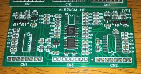
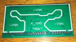
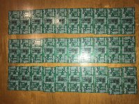
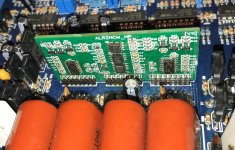
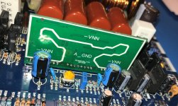
I ended up reverse engineering the driver board like other have, with a few minor changes and had some manufactured. The changes was nothing significant and included correctly connecting the unused portion of the TL072, slightly thicker traces throughout and also slightly larger pad footprints for the IRS21844s, that should make it a little easier to replace drivers in future.
I used Texas Instrument devices and had to add the 2903, a 5% NP0 capacitor in the feedback path, and the 21844s myself.
I have a good understanding of this particular design, because of this repair.
Thanks again for all the help!
Hi All,
First off, thank you all for your help and insight in this repair. I appreciate it so much!
Perry, I also initially though it must be probe settings, but alas it was not. I continued to see voltages on pin 2 of the IRS21844s and eventually came to the conclusion, after removing allot of components, that the PCB itself had become conductive. This is without any visible defects.
I ended up reverse engineering the driver board like other have, with a few minor changes and had some manufactured. The changes was nothing significant and included correctly connecting the unused portion of the TL072, slightly thicker traces throughout and also slightly larger pad footprints for the IRS21844s, that should make it a little easier to replace drivers in future.
I used Texas Instrument devices and had to add the 2903, a 5% NP0 capacitor in the feedback path, and the 21844s myself.
I have a good understanding of this particular design, because of this repair.
Thanks again for all the help!
Attachments
I would not have seen that. The circuits for pin 2 of the ICs are not connected on the driver board and nowhere near high voltage for leakage, as far as I can see. After removing all components, what was pin 2 leaking to to get 60v?
After removing components it only got up to 7V. I also did not suspect the PCB, for the same reason you mention, that there is nothing in that area that could pull it to the analog ground for example.
It also varied between the two IRS21844s with U7 at 7V and U5 at a lower voltage initially V5 and slowly dropping without IRS21844s. With the new PCB they are both at 0.002V without IRS21844s installed.
Looking at the schematic and the PCB I still could not identify what caused the observations. I am just glad that it is working. This took an extensive amount of time and in future I will likely just replace the driver card if I get another one of these to repair. Naturally all other components on the main board will be verified also.
Hopefully this can also help others!
Are u willing to sell any of the driver cards?After removing components it only got up to 7V. I also did not suspect the PCB, for the same reason you mention, that there is nothing in that area that could pull it to the analog ground for example.
It also varied between the two IRS21844s with U7 at 7V and U5 at a lower voltage initially V5 and slowly dropping without IRS21844s. With the new PCB they are both at 0.002V without IRS21844s installed.
Looking at the schematic and the PCB I still could not identify what caused the observations. I am just glad that it is working. This took an extensive amount of time and in future I will likely just replace the driver card if I get another one of these to repair. Naturally all other components on the main board will be verified also.
Hopefully this can also help others!
- Home
- General Interest
- Car Audio
- Twisted Sounds TS3.5KW Advice.