It would be great to have a single correct answer, but of course there rarely is a single correct answer, more like a whole bunch of answers that work for some folk and don't work for others - Ah well.
My CURRENT setup is: I have six inputs going to an Elma selector, from there to a stepped attenuator, then into my Aikido. My initial problem was how to deal with all this wiring while avoiding a spider-web.
I took a twisted pair from each Signal+ to the Elma selector, then a single twisted pair from the Elma to the attenuator, another single twisted pair from the attenuator to the PCB signal input.
For the Signal GND, I used 18 gauge solid core copper wire and bussed it along all the RCA GNDs directly into the PCB signal input GND (marked as input -ve on the PCB).
I still have a little hum at 60Hz which varies with volume setting.
MY QUESTION IS:
how best to use twisted pairs? I have access to Cat5e cable. Should I take a single twisted pair for each input RCA and connect 1 of the pair to SIGNAL+ and the other to SIGNAL- ?? I suppose that I could join all the respective SIGNAL -ve's saving me having to solder 6 single wires to the PCB.
I suppose that I should not worry unduly about this until I have the DC heaters wired and can be sure that hum is not caused by AC heating.
Charlie
OK, here's how I wired up my (dead-silent) Aikido grounds:
All input grounds isolated from chassis and connected together channelwise (i.e., all left input grounds connected together, all right input grounds connected together).
Wiring to selector switch used a mike cable with two twisted pairs inside a shield. I used one twisted pair per channel. (Yes, running them together inside the cable does reduce high frequency separation. I find that subjectively better, but nonetheless, this isn't germane to the grounding and can be separated if you're a "numbers" guy)
At the input end, each twisted pair is connected to the respective input jack. The shield is not connected at that end.
At the board end, for the 1st input pair, the shield is connected to the board overall ground near the input; the return wires of each twisted pair are connected to their respective board input grounds.
For the other inputs, the shield is not connected the the jack end but is connected at the same board overall ground as the first pair of inputs. At the input end, only the input "hot" wire is connected. And only that "hot" wire is connected at the selector switch end (i.e., the "return" wires of the twisted pairs are unused).
The power supply ground from the PS board is returned to the PS ground on the Aikido board. The resistive divider to elevate the heaters is on the PS board, grounded to the single-point PS ground. The lower resistor in the string is bypassed by a 10u/100V electrolytic.
The overall ground on the Aikido board is conected to chassis ground through a small (10R) resistor.
The outputs are taken with two unshielded twisted pairs connected to the appropriate terminals on the Aikido board, and to their respective grounds at the (isolated from chassis) output jacks.
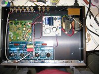
Here's a photo of the innards with the first input connected but before wiring up the other 5 inputs. The board at the upper left is not part of this discussion, it's a low pass filter for subwoofers.
All input grounds isolated from chassis and connected together channelwise (i.e., all left input grounds connected together, all right input grounds connected together).
Wiring to selector switch used a mike cable with two twisted pairs inside a shield. I used one twisted pair per channel. (Yes, running them together inside the cable does reduce high frequency separation. I find that subjectively better, but nonetheless, this isn't germane to the grounding and can be separated if you're a "numbers" guy)
At the input end, each twisted pair is connected to the respective input jack. The shield is not connected at that end.
At the board end, for the 1st input pair, the shield is connected to the board overall ground near the input; the return wires of each twisted pair are connected to their respective board input grounds.
For the other inputs, the shield is not connected the the jack end but is connected at the same board overall ground as the first pair of inputs. At the input end, only the input "hot" wire is connected. And only that "hot" wire is connected at the selector switch end (i.e., the "return" wires of the twisted pairs are unused).
The power supply ground from the PS board is returned to the PS ground on the Aikido board. The resistive divider to elevate the heaters is on the PS board, grounded to the single-point PS ground. The lower resistor in the string is bypassed by a 10u/100V electrolytic.
The overall ground on the Aikido board is conected to chassis ground through a small (10R) resistor.
The outputs are taken with two unshielded twisted pairs connected to the appropriate terminals on the Aikido board, and to their respective grounds at the (isolated from chassis) output jacks.
Here's a photo of the innards with the first input connected but before wiring up the other 5 inputs. The board at the upper left is not part of this discussion, it's a low pass filter for subwoofers.
Attachments
- Status
- Not open for further replies.