Hello DiYAudio!!!
I haven't been part of a message board in over 10 years (I'm 35) so it's very cool to be here now. 🙂
I'm moderately versed in most areas of tech, but haven't worked much on individual circuit board components/testing.
I'm a JBL JRX225 PA main that has a working tweeter, but nothing out of the dual 15" woofers. I've taken speaker wires from an existing home theater set up and ran them directly to each cone which produced clean audio.
Therefore, I assume that my issues resides in the crossover. I've pictures of the crossover that I can upload a little later but I'm primarily working with a 3.6uf cap, 10uf cap, and an 18uf cap. There is also a 10w 16ohm ceramic resistor in there.
Aside from unsoldering and removing each component from the crossover board, is there a way to test each component individually with only a multimeter? I assume I've a bad cap, but am concerned to order parts, perform the soldering, and then discover it to not be the problem.
Thank you so very much for your time and recommendations. I'm looking forward to being a member here. Thank you! 🙂
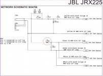
Only the 18uF capacitor is in the woofer circuit, but it is a shunt component and would not
stop the sound if it were open circuit. If it were shorted, your meter could check that.
Check the series inductor, L1 260uH, for continuity. Also check for bad connections
somewhere between the input connectors and the woofer terminals, on both hot and cold leads.
http://www.jblproservice.com/pdf/JRX200 Series/JRX225.pdf
Last edited:
Thank you so much for the quick response and the specifics around the 18uf cap. I failed to mention that I also have pics of the crossover unit if it would help. I'll let you know what I discover. Thank you again and if anyone has anything to add, I love the learning experience. 😊
If you measure resistance across the 1.5mH inductors you should measure around 1 ohm. Inspect these parts for signs of heat damage.
If you measure across the 18uF capacitor you might expect to see around 3 ohms. (with everything connected, but you can disconnect from the amp)
If you measure across the 18uF capacitor you might expect to see around 3 ohms. (with everything connected, but you can disconnect from the amp)
For a woofer this is a clear sign that you have an open circuit somewhere (broken or disconnected wire, bad solder joint or disconnected coil). So you have to check every leg of the circuit to find the broken part, but since the problem is with both woofers I'd check first the wires from the terminal to the 1.5 mH coil. When checking my soldering points I use an ohmmeter on two adjacent components trying to read 0 Ohm (or close to 0). For example you should read 0 between the terminal and the coil (leg near the terminal), or roughly 1 Ohm between the terminal and the coil but on the leg near the woofers.I'm a JBL JRX225 PA main that has a working tweeter, but nothing out of the dual 15" woofers. I've taken speaker wires from an existing home theater set up and ran them directly to each cone which produced clean audio.
Hope this helps.
Ralf
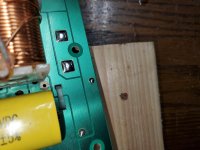
Mr. Blake, I think you nailed it. I tested and lost continuity after L2 to the speaker terminals. I discovered L2 was very loose at it's solder point, to the point that you could just slide your fingernail under it I'm including a picture as when going to resolder, pulling out the loose side of L2 pulled a chunk off the board. How do I repair this? Can I just solder it back down? Thank you all again for helping a noob out.
Attachments
Just posting an updated pic of the board with the broken point circled. My assumption is that this speaker was dropped at some point cause this damage. The included pic has the original hole circles along with the piece that came off of the board. Is this fix as easy as simply resoldering to the same spot? Thank you all again for your help! 😊
Attachments
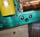
If you've determined that there is no other damage, cracking, shorting then clean the area and re-solder. Then ensure that there is mechanical stability for the future. That might include cable ties, or it might involve securing the board to a more solid surface considering the weight of the inductors. Normally that kind of weight can cause excessive flexing of the PCB.
I just wanted to post an update and thank everyone. I was able to scrape a bit of the green solder mask around the hole removing the old component created and resolder to the board. Luckily, the damage wasn't great enough to impede uncovering some copper to solder to. Everything seems to be working perfect. Thank you so much for all of your time and help in assuring me with this. I appreciate it so much. ������
- Home
- Loudspeakers
- Multi-Way
- Tweeter works, woofers do not on JRX225