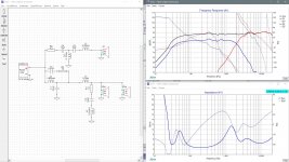
I did some sims up for the this SB MTM speaker this week but I kept getting distracted with other things and didn't get a chance to post 'till now. Pic 1 below is how that MTM sims with the spec sheet data and the original xo. The correlation is actually quite good between this and the in-cabinet measured data which says a lot about the validity of SB's spec sheets, for these drivers anyway. In my sim, the tweeter comes out just a little hot but I'm not willing to call this a problem as it just might be a small difference in the data or an artifact of my sim process.
Nothing wrong with the xo btw. It does what it's supposed to and every component except for perhaps that series inductor on the tweeter is needed. Perhaps that inductor isn't needed at all or if it is, a small cap of about 4mH in parallel before the driver will also do about the same job as well.
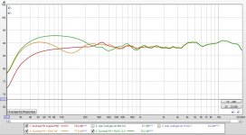
Next I looked at the effect of rear wall gain on the speaker depending on placement. Pic 2 shows what the effects of placing the front of the speaker about 36" out from the rear wall would be vs placing it right up against the rear wall which would be 13.5" from the wall. Red is the original summed response for the MTM.
Orange is let's call it a typical room placement, 36" out from the wall which looks fine except for the suck out at about 130Hz which just is what it is.
And green is the ungainly offspring of placing the speaker up against the wall. Not really very pretty. This time the suck out has moved up to about 400Hz but is a little milder, but the sub 100Hz increase in LF's in the 36" case has now increase by a solid 4dB and moved up into the lower mids too. That is not going to sound quite right me thinks without making some changes to the xo and changes to the cabinet dimensions probably as well. I did some further sims to improve the on-wall response but the best I could get required that the cabinet dimensions change to something in the ballpark of 13x27x13.5" (WxHxD) - a smaller cabinet because you wanted to go sealed I think. So that's a fairly different looking beast. Let me know if that interests you (or not) and I can give you some further info about the xo that I came up with.
Nothing wrong with the xo btw. It does what it's supposed to and every component except for perhaps that series inductor on the tweeter is needed. Perhaps that inductor isn't needed at all or if it is, a small cap of about 4mH in parallel before the driver will also do about the same job as well.
Next I looked at the effect of rear wall gain on the speaker depending on placement. Pic 2 shows what the effects of placing the front of the speaker about 36" out from the rear wall would be vs placing it right up against the rear wall which would be 13.5" from the wall. Red is the original summed response for the MTM.
Orange is let's call it a typical room placement, 36" out from the wall which looks fine except for the suck out at about 130Hz which just is what it is.
And green is the ungainly offspring of placing the speaker up against the wall. Not really very pretty. This time the suck out has moved up to about 400Hz but is a little milder, but the sub 100Hz increase in LF's in the 36" case has now increase by a solid 4dB and moved up into the lower mids too. That is not going to sound quite right me thinks without making some changes to the xo and changes to the cabinet dimensions probably as well. I did some further sims to improve the on-wall response but the best I could get required that the cabinet dimensions change to something in the ballpark of 13x27x13.5" (WxHxD) - a smaller cabinet because you wanted to go sealed I think. So that's a fairly different looking beast. Let me know if that interests you (or not) and I can give you some further info about the xo that I came up with.
Attachments
Outboard crossovers are a very good thing. And if your forte is woodworking you can match them to the speaker cabinets. Separate connectors for each section also means the speakers are immediately ready for Bi/Tri-amping if that was a possibility in the future. Has many benefits I am told.
I do have a couple of external crossovers and they do need box covers to hide my ugly and untidy wiring. If you do this don't forget to ventilate some.
I do have a couple of external crossovers and they do need box covers to hide my ugly and untidy wiring. If you do this don't forget to ventilate some.
Hi Moondog55 yes I had decided to fit the crossover externally on the back of each speaker so that I could make changes if required.
Thank you for spending so much time on the crossover design, it good to know that it is basically ok.I did some sims up for the this SB MTM speaker this week but I kept getting distracted with other things and didn't get a chance to post 'till now. Pic 1 below is how that MTM sims with the spec sheet data and the original xo. The correlation is actually quite good between this and the in-cabinet measured data which says a lot about the validity of SB's spec sheets, for these drivers anyway. In my sim, the tweeter comes out just a little hot but I'm not willing to call this a problem as it just might be a small difference in the data or an artifact of my sim process.
Nothing wrong with the xo btw. It does what it's supposed to and every component except for perhaps that series inductor on the tweeter is needed. Perhaps that inductor isn't needed at all or if it is, a small cap of about 4mH in parallel before the driver will also do about the same job as well.
Next I looked at the effect of rear wall gain on the speaker depending on placement. Pic 2 shows what the effects of placing the front of the speaker about 36" out from the rear wall would be vs placing it right up against the rear wall which would be 13.5" from the wall. Red is the original summed response for the MTM.
Orange is let's call it a typical room placement, 36" out from the wall which looks fine except for the suck out at about 130Hz which just is what it is.
And green is the ungainly offspring of placing the speaker up against the wall. Not really very pretty. This time the suck out has moved up to about 400Hz but is a little milder, but the sub 100Hz increase in LF's in the 36" case has now increase by a solid 4dB and moved up into the lower mids too. That is not going to sound quite right me thinks without making some changes to the xo and changes to the cabinet dimensions probably as well. I did some further sims to improve the on-wall response but the best I could get required that the cabinet dimensions change to something in the ballpark of 13x27x13.5" (WxHxD) - a smaller cabinet because you wanted to go sealed I think. So that's a fairly different looking beast. Let me know if that interests you (or not) and I can give you some further info about the xo that I came up with.
I dont intend to make them wider due to WAF so that option is out of the question.
Did you base your calculations on the fact that I intend to use the Satori TW29 R tweeter in lieu of the SB29RDC.
The brightness may not be a problem with the different tweeter and in any case I have HF hearing loss.
In an earlier post raymond gave me ideas on how to reduce the baffle step etc which is what I would probably do.
With regard to the small coil in the tweeter section do you think it would be best to leave it.
If you do have some time to spare I would be interested in a completely redesigned crossover incorporating the new tweeter and a reduction in baffle step.
Thank you again for your help it is very welcome.
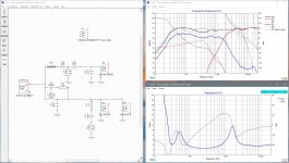
First, no guarantees here. Accuracy is best achieved by doing measurements in situ. But since the original xo response shows very good similarity to the simulated response using the spec sheet data, there is a good chance the following will be at a minimum a very good starting point.
So I based the changes on the summed FR of the original xo. Then I added in the rear wall gain of a typical speaker position, about 3' out into the room. This became my new target curve (grey curve in the pic below).
Next I added in to the spec curves the baffle diffraction effects and then the effects of rear wall gain at 13.5" from the back wall and re-worked the xo. Note that I still used the curves with the vented box alignment because I'm lazy and because going sealed won't make a difference to the xo in this situation. This time the tweeter is the Satori TW29R. The spec sheet suggests the levels are slightly different but AudioExcite's measurements suggest they are pretty much the same. Since I used the spec curves, experimenting with R2 and the tweeter level may be a prerequisite. I'd try 1ohm and then maybe 2ohm and possibly try .5ohm variations too if I wanted to be picky.
There are a few small changes to both the tweeter and woofer xo's. I changed the original tweeter series inductor to a parallel capacitor to tame the slightly rising response. Just in case it's hard to see, C6 is 1.2uF not 12 but you may want to try it without at first and see how that sounds.
The challenge in this situation was trying to keep the minimum impedance above 3ohm which should be about the minimum for a 4ohm nominal speaker. To do that I needed to use a slightly higher than usual .4 ohm DCR on the woofer's series inductor, L1. In terms of the FR, you are getting a suckout now centered around 330Hz which is the main effect of the on-wall placement and nothing the xo can really help.
Two other things to note. First try to make sure that the speakers are not the same 13.5" from the side walls. That will just reinforce that 330Hz suckout. And second as has been mentioned by someone else, placing the speaker right up against a wall is going to reinforce the lengthwise room modes. Because these standing waves are always loudest at the reflecting boundaries, ie. nearest to the walls, the worst place you can put your listening position is also up against the back wall. Depending on the size of your room, if you go sealed the 1st and maybe the 2nd modes are going to be below the speakers' F3 so you don't have to worry about those. For the 3rd and 4th modes, you are best sitting somewhere between about 1/4 to 1/5 of the room length from the back wall because that will put you closer to the nulls of those standing waves so they won't be as bad of a problem.
The zipped XSim file is attached if you want to play around with it at all.
Attachments
jreave you are truly a great forum member and have given me some incredible help.
I do have a few questions as follows.
If I download the xsim file do I need to have the programme on my computer to do anything, I dont have it at the moment.
Having spent sometime discussing the problems with the lady of the house (boss) I may be able to change the lounge around to get the speakers out from the back wall nearly the full amount of 36inches to eliminate going to a complete crossover change and therefore keep the original design.
But I would prefer to do away with the little coil in series with the tweeter and wondered what the value of the capacitor would be in parrallel with the tweeter as per your revised crossover, of course bearing in mind that it would be the Satori one.
I assume that it would be a different value to the revised crossover as the overall level would be lower.
Also do you think the original crossover is ok with the Satori, I think most people think that it is a drop in replacement.
Thank you again
Yes, I think you will need to download XSim first before you can open the file.
So with the original xo, I'm finding that the series inductor works better than the parallel capacitor this time on the Satori tweeter. The value is reduced though to .033mH. You may need to buy a slightly larger value though, (.05mH is about the smallest from my local supplier) and then unwind it until you get the correct value. You'll need a way to measure impedance in order to do that though. It looks better too with it than without it.
The Satori looks pretty similar. Using the spec sheet curves for both tweeters, this time I just altered the caps a tiny bit to match the summed response from the original. You can try both versions if you want and see if you hear any differences. And again, play with the value of R2 until you are satisfied.
As before, pic of the xo and the zipped XSim file are attached.
Attachments

Hi jreave thank you again very kind of you to spend time on this for me.
Does xsim give dcr values for the coils and also should I add the values of both coils dcr together to give me a series resistance when sizing my speaker box
Does xsim give dcr values for the coils and also should I add the values of both coils dcr together to give me a series resistance when sizing my speaker box
Yes, the DCR of the coils will be in XSim. But also check the original write-up for those speakers. That's what you should use. I wasn't that exact in my sims so my values may be a touch off. But if you open XSim, you can change the values yourself and see if they make any real differences. Sometimes they do and sometimes they don't.
Yes, the series coil DCR added together plus the DCR of the speaker wiring can go into the box modeling programs. It might get up to .4 or .5ohm. But don't sweat it - it won't make much of a difference to a sealed box.
Yes, the series coil DCR added together plus the DCR of the speaker wiring can go into the box modeling programs. It might get up to .4 or .5ohm. But don't sweat it - it won't make much of a difference to a sealed box.
Hi jreave thanks for all your valuable help.
Actualy a high series resistance does make quite a difference with these drivers I was going to make a 38 litre cabinet but with 0.5 ohms series resistance it goes up to about 52 litres with a qtc of 0.7.
No problem though I can stuff it quite a bit and it will not matter much if its 0.75 qts.
BTW I live in the UK but have been to Canada quite a lot skiing and touring I love it there and have always found the people there to be very very friendly and you have proved that again.
Fair enough.
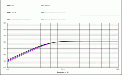
Run the numbers through a modelling program and the Vb doesn't change a fair amount. I guess what I was trying to say is that the actual FR does change nearly as much in comparison to similar changes to a vented box. It can vary with the driver in question, but with these SB17's, if the Q is .7 or .65 or .75, there isn't a whole lot of difference in the actual FR. You'll get about 1 dB more at 40Hz with Q =.65 over Q = .75, but it doesn't even look like 1/2dB difference at 40Hz between Q =.7 and Q = .65. and that's it. See pic below and also note the fairly large differences in Vb for the different Q's. Sims are in Unibox and all 3 cases are with heavy fill.
Btw, woofer inductor DCR in the original adds up to .28ohm. Also I get slightly different Vb from Unibox for 2 x SB17NAC35-8. All cases again with heavy stuffing and using .38ohm for series resistance (assuming .1ohm for cable resistance), for Q=.7, it suggests Vb=31L with F3=53Hz. For Q=.65, Vb=42L and F3=52Hz. And for Q=.6, Vb=63L and F3=52Hz.
Also, I can't tell exactly how deep your knowledge is, so just in case --> Capacitors add together when they are wired in parallel. So buy 1uF, 2uF, 9uF and 10uF and you can easily try the tweeter filter out with a 10uF and 10uF combination as well as a 9uF and 12uF combination. Resistors on the other hand add together when they are in series. So I'd buy 2 x .5ohm and 2 x 1ohm and that should give you the leeway to play around in between .5ohm and 2ohm of series resistance on the tweeter.
Hope you made the trips all the way out to the British Columbia - that's where the magic is.
Attachments
Hi jreave thanks again for your help.
Yes been to BC a few times have been skiing in Banff and Whistler always had great times there.
Yes been to BC a few times have been skiing in Banff and Whistler always had great times there.
Awesome. I lived in Whistler for about 20 years.
Sorry, I just noticed a rather important typo in my last post: "Run the numbers through a modelling program and the Vb doesn't change a fair amount." --> "doesn't" should have been "does". 😱
Sorry, I just noticed a rather important typo in my last post: "Run the numbers through a modelling program and the Vb doesn't change a fair amount." --> "doesn't" should have been "does". 😱
Yes, I think you will need to download XSim first before you can open the file.
So with the original xo, I'm finding that the series inductor works better than the parallel capacitor this time on the Satori tweeter. The value is reduced though to .033mH. You may need to buy a slightly larger value though, (.05mH is about the smallest from my local supplier) and then unwind it until you get the correct value. You'll need a way to measure impedance in order to do that though. It looks better too with it than without it.
The Satori looks pretty similar. Using the spec sheet curves for both tweeters, this time I just altered the caps a tiny bit to match the summed response from the original. You can try both versions if you want and see if you hear any differences. And again, play with the value of R2 until you are satisfied.
As before, pic of the xo and the zipped XSim file are attached.
Hi jreave
I have downloaded xsim and played about a bit.
I was thinking of reducing the 0.825mH baffle step inductor a fraction to 0.8mH.
On the subject of DCR it is currently 0.16 ohms and the minimum impedance is 2.67ohms, do you think I should increase the DCR to say 0.3ohms to get the impedance up a little.
Thanks
Going to .8mH doesn't make a large difference so that would be fine. Just fyi, the values of L1 and C3 work together to target the woofer cone resonance so if you change 1 you would usually have to change the other. Here the L3 change is small enough and the attack on the resonance doesn't have to be quite so exact so that no change is required on C3.
I guess the DCR of L1 depends on your amp but I doubt your amp is going to care that much if the minimum impedance is 2.67ohm or ~2.83ohm.
I guess the DCR of L1 depends on your amp but I doubt your amp is going to care that much if the minimum impedance is 2.67ohm or ~2.83ohm.
Hi jreave
Thanks, actually I forgot to say that I would also like to change C3 to 0.56 uF is that OK also.
Thanks, actually I forgot to say that I would also like to change C3 to 0.56 uF is that OK also.
Hi jReave
I have made some minor changes to the crossover wonder if you could have a quick glance and let me know if there is anything bad with my changes.
Both coils (inductors) on the HF circuit are 18g (1.0mm) is that ok
Thank you
View attachment Xsim New Crossover.zip
I have made some minor changes to the crossover wonder if you could have a quick glance and let me know if there is anything bad with my changes.
Both coils (inductors) on the HF circuit are 18g (1.0mm) is that ok
Thank you
View attachment Xsim New Crossover.zip
Last edited:
Because these sims are not using real measurements but instead are based on the spec sheet curves compared to the original measured response, what's important to note is that the target curve isn't the flattest summed response (which is what would normally be the correct starting point), but is instead the simulated summed response with the original xo. So that response is loaded into driver S5 and what you do to display it is go to 'Curves' in the Frequency Response window and select 'S5(driver only)'. So that is the shape you are trying to match with the new xo.
Also note that in the spec sheets the SB29RDC tweeter runs just a little bit hotter than the Satori so if anything, you will need to reduce R2 not increase it. so allow your summed response to be just a little higher than the target curve for the tweeter response.
So with that info, I would prefer that R2 get changed in the opposite direction to ~1ohm and that a change in C4 doesn't also increase the tweeter output in the rolloff region which is what 10uF will do instead of 9uF. So I would prefer C4 stays at the original 9uF.
Coil changes look fine though.
But again, you can purchase smaller vales of caps and resistors and make up a few different combinations and then you decide which sounds best.
- Home
- Loudspeakers
- Multi-Way
- Tweeter / Crossover Advice