Ok, so I had simulated the crossover as it is and with 2.2uF capacitor, look what I got. Isn`t this to big of a hole in frequency response?Ok, but what will happen with cut off frequency if I change it? Will it stay the same?
As it is now, 7uF

Capacitor changed to 2.2uF

diy1995,
I believe the first thing you should do is buy 2, 50watt variable Lpads ( each wired up between the HiPass section of your existing network and the compression driver ).
Here's one available from an outfit in Germany.
50 watt, Variable Lpad from Strassacker
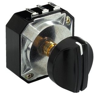
Here's how to wire it up within a typical horn circuit.

While you're spending money ( on this stuff ) order a few pairs of 10 watt resistors, in values something like these ( 30R, 20R, 16R, 12R, 10R, 8R, 6R, 4R, 2R, 1R ).
Those will give you a decent start for building & modifying existing networks.
Having the ability to turn down ( balance ) your horns to your low-efficiency woofers is an important first step ( to creating something listenable ).
After that you're going to need to fix the EQ curve on that horn/driver combo.
🙂
I believe the first thing you should do is buy 2, 50watt variable Lpads ( each wired up between the HiPass section of your existing network and the compression driver ).
Here's one available from an outfit in Germany.
50 watt, Variable Lpad from Strassacker
Here's how to wire it up within a typical horn circuit.
While you're spending money ( on this stuff ) order a few pairs of 10 watt resistors, in values something like these ( 30R, 20R, 16R, 12R, 10R, 8R, 6R, 4R, 2R, 1R ).
Those will give you a decent start for building & modifying existing networks.
Having the ability to turn down ( balance ) your horns to your low-efficiency woofers is an important first step ( to creating something listenable ).
After that you're going to need to fix the EQ curve on that horn/driver combo.
🙂
If you keep the 20ohm resistor without a bulb bypass you will not be able to maintain the approx. 8ohm impedance of the L pad suggested by " system 7 " . At present the 20 ohm is giving 11dB attenuation to the tweeter . A 5R6 in series with the tweeter and 2R7 across the tweeter will give 18.5dB atten. ( with 20ohm and bulb in place ) and you can go lower than 2R7 . I think I have done my maths correctly .
Cutoff frequency depends on impedance (vs frequency) and acoustic frequency response of the driver (plus horn), and on values of the capacitor and the inductor. Because we don't know anything of this, except the capacitor value (regardless if it is 2.2 or 7 uF), than we can only hope the cutoff frequency will be complementary to that of the midbass. Anyhow, it will sound much better with 2.2 uF.Ok, but what will happen with cut off frequency if I change it? Will it stay the same?
That would be a hole only if the drivers have identical sensitivity (which they haven't) and if the drivers are 8 ohm resistors (which they are not) and if the drivers have an ideal frequency response flat from 0 Hz thru infinity (which they haven't).Ok, so I had simulated the crossover as it is and with 2.2uF capacitor, look what I got. Isn`t this to big of a hole in frequency response?
Ok, I see a few suggestions. I agree that variable l-pad would be the easiest way to go, but I have kinda tight budget as a student, so I always try to get things made as cheap as possible.
I will fit new bulbs (fuses), but can anyone tell me what value should I use, writing on the bulbs is really blurry, so I don`t know that value are those and I don`t know why bulbs blew in the first place, god knows what previous owner was doing. And if I understand correctly bad bulb makes resistance of whole speaker go up and this also makes woofers recieve less power from the amp because impedance is higher?
So I will fit bulbs, fit 5R6 in series and 2R7 across the tweeters, what about capacitor, should I change if from 7uf to 2.2uf or not?
And after that there comes fixing the EQ curve, can I do that if I don`t have any measuring equipment?
Thank you all 🙂
If the intended use of your speaker is home HiFi ( & I hope it is with that low-efficiency woofer ) I would recommend forgetting about the bulb and just replacing it with a piece of wire.
These bulb/resistor safety networks are common in semi-pro PA boxes ( where there's typically not enough gear speced to do the job & what is there is over-driven to the max ).
The bulb blows ( to save the HF driver ) while the resistor still allows some signal through ( at a much reduced level ) signalling the operator that there's a problem.
🙂
If the intended use of your speaker is home HiFi ( & I hope it is with that low-efficiency woofer ) I would recommend forgetting about the bulb and just replacing it with a piece of wire.
These bulb/resistor safety networks are common in semi-pro PA boxes ( where there's typically not enough gear speced to do the job & what is there is over-driven to the max ).
The bulb blows ( to save the HF driver ) while the resistor still allows some signal through ( at a much reduced level ) signalling the operator that there's a problem.
🙂
Unfortunately I will be using this for PA. Nothing special up to 20 people, 100m2, outside, at normal listening level and some banging from time to time. But speakers are really loud anyways, for normal listening outside I set pots at 1/4 on my zeck pt7 amplifier (rated 2 x 450w @ 8ohm), at home I move pots for 1-2mm from minimum and it`s already too loud for normal listening. However I can turn pots all the way up and sound is still clean, no distortions, only problem is with too loud tweeters (at all volume settings).
In the future I will repleace the drivers and build horn woofers out of old ones, or I will build horn woofers with new drivers and keep old drivers as they are now.
Can I use film capacitors like one on the photo? For repleacing 7uf with 2.2uf?

That is the only one I can get in store near me.
That is the only one I can get in store near me.
Last edited:
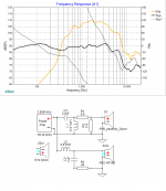
Here's a pic showing what's likely going to be the response of your system with an HF driver ( like you've shown ).
I've used a known phenolic diaphragmed midrange driver that I figure has a slightly larger diaphragm than what yours has ( 50mm vs 25 or maybe 44mm ). The smaller the diaphragm the higher the driver should go ( with compromised low-end ).

The orange trace is the mid-driver before any attenuation ( yours might go higher / though unlikely much beyond 10K ).
I've included a zipped XSim file for you to play with ( play with the LCR values as an educational exercise ).
XSimSetup.exe download
🙂
PS: Film caps are preferred.
I've used a known phenolic diaphragmed midrange driver that I figure has a slightly larger diaphragm than what yours has ( 50mm vs 25 or maybe 44mm ). The smaller the diaphragm the higher the driver should go ( with compromised low-end ).
The orange trace is the mid-driver before any attenuation ( yours might go higher / though unlikely much beyond 10K ).
I've included a zipped XSim file for you to play with ( play with the LCR values as an educational exercise ).
XSimSetup.exe download
🙂
PS: Film caps are preferred.
Attachments
Thank you. I have played a bit to see what happens, with and without l-pad, with and without the bulb and with different capacitor values.Here's a pic showing what's likely going to be the response of your system with an HF driver ( like you've shown ).
I've used a known phenolic diaphragmed midrange driver that I figure has a slightly larger diaphragm than what yours has ( 50mm vs 25 or maybe 44mm ). The smaller the diaphragm the higher the driver should go ( with compromised low-end ).
The orange trace is the mid-driver before any attenuation ( yours might go higher / though unlikely much beyond 10K ).
I've included a zipped XSim file for you to play with ( play with the LCR values as an educational exercise ).
XSimSetup.exe download
🙂
PS: Film caps are preferred.
I see how big of a disaster it is as it is now
 I will go with the bulbs fitted, 2.2uf and 5k6 resistors (the example that you send me), Just by looking at frequency response I can already imagine how it will sound alot better.
Oh, I misslooked that... I recently started using 5k6 instead of 5.6k and now everything looks 5k6 to meThe resistors used are 5.6 ohms ( not 5600 ohms ).

Thank you for correcting me.
One can write 5.6 ohms as 5R6 ( in that style of shorthand ).
The danger is the "R" so closely resembles a "K" ( that substitution mistakes are bound to occur ).
The danger is the "R" so closely resembles a "K" ( that substitution mistakes are bound to occur ).
One can write 5.6 ohms as 5R6 ( in that style of shorthand ).
The danger is the "R" so closely resembles a "K" ( that substitution mistakes are bound to occur ).
This can be the problem 🙂
I have found that additional capacitors in series with the tweeter (that I mentioned in the first post) are not 0.15uF, but 3.3uF, I dropped those values in capacitor calculator and both together in series are 2.24uF.
Should I change to single 2.2uF anyway? Those caps looks higher quality than what I would be albe to get, that`s the reason I would keep 7uF + 3,3uF as it is.
The ( technical ) answer to that question is something that you can determine for yourself ( by swapping in those values within XSim ).
🙂
Well tehnicaly it is the same. So I will let it be-The ( technical ) answer to that question is something that you can determine for yourself ( by swapping in those values within XSim ).
🙂
Your crossover network connects the speakers in parallel and the bulb is only in the tweeter circuit so a bad bulb only affects the level received by the tweeter , it only raises the impedance of the tweeter circuit when it has blown . As already mentioned it is there to protect the tweeter from being overdriven.
Last edited:
- Status
- Not open for further replies.
- Home
- Loudspeakers
- Multi-Way
- Tweeter attenuation