Thanks for the transistors suggestion.
I first thought on something more "usual" like 2n3904, but unfortunately their Vce rating is only 40V. I need something like 70-100V (Vcc modulator + (-Vrail max) + some margin)
I first thought on something more "usual" like 2n3904, but unfortunately their Vce rating is only 40V. I need something like 70-100V (Vcc modulator + (-Vrail max) + some margin)
Pierre said:Thanks for the transistors suggestion.
I first thought on something more "usual" like 2n3904, but unfortunately their Vce rating is only 40V. I need something like 70-100V (Vcc modulator + (-Vrail max) + some margin)
My mistake you're right, I thought that 6.3 was referenced to the negative rail as well... sorry 🙂
BTW I like your decoupling.
Chris,
Now that you mention it, I forgot to include the main rails supply decoupling in the posted sch: it consists on a 220uF/100V/105ºC capacitor in parallel with a ceramic 100nF/100V SMD capacitor for each rail to GND, very near the mosfets.
Now that you mention it, I forgot to include the main rails supply decoupling in the posted sch: it consists on a 220uF/100V/105ºC capacitor in parallel with a ceramic 100nF/100V SMD capacitor for each rail to GND, very near the mosfets.
Charles, about NFB:
The response looks quite good experimentally. With resistive loads, there is no trace of inestability at any point of the signal. Sound is very good for my taste also. The only hint observed is some HF oscillation at certain high amplitudes with my test loads (JBL TR225 2x15"+tweeter), perhaps they are too complex.
Is that normal/acceptable?
Salut Pierre
Do you have any possibility to use a dummy load that shows about the same impedance as the speaker box above the audible range ? This would be convenient for testing of loop stability.
Regarding the level shift transistors: They can be operated faster if used as common base - but this would make more changes to the circuit necessary.
The soft start solution I was talking of would also need quite some circuit effort in your case.
It could be implemented easier whith a topology that uses two comparators to achieve tuneable dead-time (i.e. window comparator) like Kanwar uses. One would just begin with infinite dead-time and gradually reduce it to the final value upon startup - this would mean the same as gradually changeing from a class-BD to a class-AD amp.
Regards
Charles
The problem here is to model the impedance of the box. Anyway, the test load should be representative of a typical load, it makes no sense to optimize the amp. for a single type of speaker.
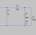
to test amps, i made a little box with some switches parallel .:
-- 8 ohm
-- 8 ohm
-- 1uf + 0,5 r
-- 0,3 mh + 2 ohm
this makes test simple: no load, 8, 4 ohm or kap or ind. load, like a speaker chassis.
-- 8 ohm
-- 8 ohm
-- 1uf + 0,5 r
-- 0,3 mh + 2 ohm
this makes test simple: no load, 8, 4 ohm or kap or ind. load, like a speaker chassis.
Very valuable suggestion, alfsch, Thanks!
From your experience, what is the typical situation for a typical box? all switches activated? (or all except one of the 8 ohm resistors for 8 ohm loads). I suppose that model doesn't include the typical crossover effects, right?
I will recalculate the simulations to see how phase margin is affected with these loads.
Best regards
With the dummy load model proposed, 8 ohm resistance, the simulations show that phase margin is reduced to around 25º.
That's quite small, so I decided to change the feedback cap from 33pF to 56pF, and that seems to improve things a lot and produce a phase margin of around 42º.
I have to test that change in the real amplifier, and then I will tell you...
That's quite small, so I decided to change the feedback cap from 33pF to 56pF, and that seems to improve things a lot and produce a phase margin of around 42º.
I have to test that change in the real amplifier, and then I will tell you...
imho typical box impedance is not useful.
more difficult for amps is cap. or ind. load, as i wrote;
cap is about like using a el.static speaker,
ind. like a bass-chassis only .
so you see r..real load (never real for real speakers 😉
cap / ind or both : load with +/- phase for current.
if a amp has no problem with any combination, you can assume, it will be stable with most or maybe all speakers.
the ind. load i use is more complex :
it simulates a bass-speaker with typical resonance...
more difficult for amps is cap. or ind. load, as i wrote;
cap is about like using a el.static speaker,
ind. like a bass-chassis only .
so you see r..real load (never real for real speakers 😉
cap / ind or both
: load with +/- phase for current.if a amp has no problem with any combination, you can assume, it will be stable with most or maybe all speakers.
the ind. load i use is more complex :
it simulates a bass-speaker with typical resonance...
Attachments
Hi Pierre,
Try this, Short the output of Error amp i.e. input of window comparator to GND and then check for any output DC Transient offset at startup.....
What are the results after AC coupling the Triangle to Comp. input???
regards,
K a n w a r
Try this, Short the output of Error amp i.e. input of window comparator to GND and then check for any output DC Transient offset at startup.....
What are the results after AC coupling the Triangle to Comp. input???
regards,
K a n w a r
Kanwar. Your proposal is welcome.
Unfortunately, I won't be doing the tests until Monday, but the last one you have proposed really worths the pain, as it will tell me to what extent the effect is due to output stage + filter estabilization or if control (NFB or offset) is the culprit.
Best regards,
Pierre
Unfortunately, I won't be doing the tests until Monday, but the last one you have proposed really worths the pain, as it will tell me to what extent the effect is due to output stage + filter estabilization or if control (NFB or offset) is the culprit.
Best regards,
Pierre
Hi Pierre,
I once had problem with the IR2113 device when its
different supplies did not come up in the right sequence.
I think that the logic supply must come up first otherwise
it may show erratic operation during power up, regardless
the state on the SD pin.
Just an idea.
/ Mattias
I once had problem with the IR2113 device when its
different supplies did not come up in the right sequence.
I think that the logic supply must come up first otherwise
it may show erratic operation during power up, regardless
the state on the SD pin.
Just an idea.
/ Mattias
Mmmm. Perhaps, but if the SD pin is enabled for a couple of seconds, you give enough time for it to estabilize, then you disable the SD pin and then (when the supplies are all ok, except bootstrap), when the click is heard.
Pierre,
OK, I see. Sorry I didn't get that. Usually when designing powersupplies
I just tie the SD pin to GND.
Keep searching / cheers / Mattias
OK, I see. Sorry I didn't get that. Usually when designing powersupplies
I just tie the SD pin to GND.
Keep searching / cheers / Mattias
Hi Pierre,
You haven't told about your problem Status...[turn-on/off transients]
Is it solved or not, if yes what type of changes have you made in your design, it would be very good for all of us to see your nice updated schematic..... and it would be quite also helpfull for diyer's knowledge bank....
cheers,
K a n w a r😉
I didn't make any changes by the moment, that's why I haven't posted anything.
The biggest improvement was made by reducing the bootstrap capacitor from 10uF to 1uF. The turn-on click is much lower now. The turn-off one is almost the same, but not very annoying.
The biggest improvement was made by reducing the bootstrap capacitor from 10uF to 1uF. The turn-on click is much lower now. The turn-off one is almost the same, but not very annoying.
Question, is there any reason for a groundloop isolator to create this type of reaction to a B / D amplifier?
- Status
- Not open for further replies.
- Home
- Amplifiers
- Class D
- Turn on/off transients