How did the new inductor get into that state? I'm beginning to wonder if you are using it properly.See the pic (left original, right new and do not care about the winding it is now winded properly)
the coil: SP coils | Visaton
0,82mH 0,52Ω
don't panic Galu. now after completely rewiring the system according to your scheme it plays all more harmonic.
it is done.
ad how did the coil get into the state: was winding it off to see if less inductance changes the sound 😛
0,82mH 0,52Ω
don't panic Galu. now after completely rewiring the system according to your scheme it plays all more harmonic.
it is done.
ad how did the coil get into the state: was winding it off to see if less inductance changes the sound 😛
Last edited:
Like your coil, I was a bit wound up!!don't panic Galu
However, after closing my eyes and picturing my happy place, I finally managed to calm down! 😀
Happy listening!
Galu i had a visitor at the sound system test room and he told me that the speaker plays almost like his stereo for 1700,- E. He just was a bit unsatisfied with the mids performance.
I have now ordered a 0.1mH coil for the Butterworth filter (you have teached me to assemble) and will attach it in series to the 12uF capacitor.
I have now ordered a 0.1mH coil for the Butterworth filter (you have teached me to assemble) and will attach it in series to the 12uF capacitor.
the new coil did not change anything. i guess the problem will be the 40y old rubber edge on the mids speaker. it did get hard.
Hi again! Where on Earth have you been? 😉
Just don't be tempted to continue playing the mid without its rubber surround as you don't want the voice coil to go off centre and start scraping in the magnetic gap. 😱
Just don't be tempted to continue playing the mid without its rubber surround as you don't want the voice coil to go off centre and start scraping in the magnetic gap. 😱
oh how are you Galu?
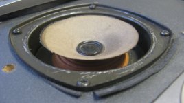
i played only silent and it is glued also on bottom (yellow/brown on picture).
i played only silent and it is glued also on bottom (yellow/brown on picture).
I'm fine thanks and hope you are too. 😎
The yellow/brown part is the rear, or bottom, suspension of the cone, also known as the 'spider'.
It has a major part to play in keeping the voice coil centered.
The yellow/brown part is the rear, or bottom, suspension of the cone, also known as the 'spider'.
It has a major part to play in keeping the voice coil centered.
i am fine thanks. will order now the 4.5 inch ring and report once i got it glued. this should be my final step in this project i hope.
will do.
also Galu can you recommend me a calculator for Butterworth 1st order?
All i could find were calculator where you have to define the frequency (and resistance) to get the capacities and inductance. but my approach is to check the frequency by using diverse capacitors to check it by ear and then calculate the inductance via calculator.
i am talking about crossover design in general. found many calculators online but they all need to define the frequency which can be tricky (frequency stated by the driver producers might not be accurate so i rely here on my ears and check how they play by trying diverse capacitors)
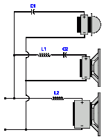
See attached 1st order crossover circuit.
If you are going to rely on your ears to select a tweeter capacitor (C1) then why not rely on your ears to select a bass inductor (L2)? I suggest you buy a selection of crossover inductors and a selection of crossover capacitors and enjoy some happy experimenting!
P.S. The midrange band pass filter (comprising series inductor and capacitor, L1 & C2) really has to be calculated. Here's a suitable calculator for this purpose: Band-pass filter 6dB per octave
Attachments
yes a set of capacitors (cheap electrolytes) i already have are enough for tuning. when a correct capacitance value is found by ears i bought the foil-caps and did calculate the inductance of the the coil based on the capacitance (like if i know C1 i can calculate L1 or if i know C2 i can calculate L2)
for me the best approach to compare the capacitance by adding multiple capacitors in parallel while playing music. this way i could hear the nuances. (example. you have 4uF and add 1uF capacitors 1 by 1. At a certain point you can hear an audible difference)
when i did try to switch the capacitors and had to cut the music for a while i was not sure if it sounded better or not.
any way thank you for introducing Sir Stephen Butterworth to me. Seams like his approach was the best (even at order #1)
Last edited:
the 4,5 inch ring did not fit either. must be because of the metric system in Belgium i guess. I glued it anyway but got to use of lot of it as i had only 1-2mm contact between the ring and the cone.
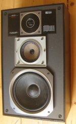
plays nice and i hope i do not have to touch it now for at least 10 year now. (did not expect that project to be so time consuming)
here is the photo and even a short video as promised.
plays nice and i hope i do not have to touch it now for at least 10 year now. (did not expect that project to be so time consuming)
here is the photo and even a short video as promised.
Attachments
Last edited:
- Home
- Loudspeakers
- Full Range
- tuning a 40 years old box made in Belgium.