Hi,
i have a melody sp3, i am running 6P3S-E power tubes, and biased it to 1.2v on the taps.
tonight i replaced a cathode resistor that was out of spec. this resolved a previous issue that caused the bias to be off. the resistor was on the right rear tube.
tonight i noticed after warming up that the two left tubes have alternating pulsing blue/purple in the tube. the right tubes have barely any blue at all in them.
i am not sure if this is a result of the repair or was happening before hand, so i was hoping to get some input.
https://youtu.be/jtkF2ClvwIU
i have not tried swapping tubes around yet. if anyone has any other ideas please let me know
Attachments
Last edited:
Your description sounds like low frequency motor boating or instability.
You state you replaced a cathode resistor that was out of spec, which one? The output valves are fixed bias, have you monitored the cathode current with no signal?
it was a 33 ohm resistor that i replaced.
i do not hear any changes in the music, i just feel that there could be an issue with the alternating pulses like as seen in the video in my first post.
it is doing it with the volume pot at 0. i will probably swap tubes around tonight to see if the problems stay with those two tubes, unless someone has some other things i should look at before i try that.
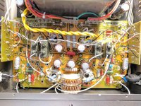
i attached an image of the internals. the resistor replaced goes across two of the pins on the power tube socket. it was measured as 33 ohm on three of them, and one of them was bad (the measurement floated around and was in megaohm, after being pulled). i replaced the resistor in the top left power tube socket on this photo
Attachments
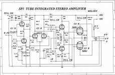
I suspect the coupling caps from the 6922 to the 12AU7 being way too big. Who really needs a LF rolloff at 0.72 Hz? Try reducing them to 0.22 or even 0.1 µF.
Best regards!
Correct me if I'm wing but you are referring to the silver cap at the front corner of the amp in the picture? Those are .1 caps
Sadly I'm not able to identify these 0.1 µF caps, 'cause they're not present in the schematics you've been showing to us in your first post. Most certainly they are input coupling caps. The capacitors I was mentioning are called C6 and C7 in the schematics. I suspect the four big grey blocks (connected to CN11, CN16, CN17, CN22, CN23, CN26 and two more points on the PCB that aren't visible) of being them.
Best regards!
Best regards!
Sadly I'm not able to identify these 0.1 µF caps, 'cause they're not present in the schematics you've been showing to us in your first post. Most certainly they are input coupling caps. The capacitors I was mentioning are called C6 and C7 in the schematics. I suspect the four big grey blocks (connected to CN11, CN16, CN17, CN22, CN23, CN26 and two more points on the PCB that aren't visible) of being them.
Best regards!
yeah this schematic is the best available, and many have pointed out its incomplete, but sadly all thats available. the big caps are .47uf.
i hate to ask but has anyone taken a look at the youtube? the oscillation of the purple inside the tube is my concern. i am going to open it tonight and start probing around and see if i see any voltage swings that are in sync with that oscillation
Sorry, after a close look I have to say that the schematics doesn't have too much in common with your actual amplifier :-(.
I had exactly the same issue in a similar amp I've designed and built about 30 years ago. The woofers' diaphragms moved in and out by the same frequency the fluorescence changed between both EL34's (in my case). I cured it by decreasing the value of the coupling caps to the power tubes' grids substantially, but without affecting bass response too much. Hence my advice to you.
Best regards!
VLF oscillation
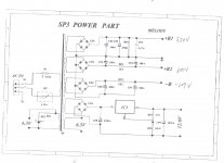
Hello from Greece! I think your circuit oscilate in very low frequency. It is out of frequency bandwith of output transformer you can not hear anything! The circuit it is not simple,it has mixed bias.First you need the measure the idle current of the power tubes,without signal. If the current changes in sync with the glow,that is not good .Second check all the electrolytic capacitors in power supply,maybe it is dry and dead,especially the negative bias supply. Third check the drive tubes,change it between channels if the problem go to the other channel the tubes is faulty,the same thing with output tubes. This problem can damage the output transformer. At last more skilled members you can help you more than me!
Hello from Greece! I think your circuit oscilate in very low frequency. It is out of frequency bandwith of output transformer you can not hear anything! The circuit it is not simple,it has mixed bias.First you need the measure the idle current of the power tubes,without signal. If the current changes in sync with the glow,that is not good .Second check all the electrolytic capacitors in power supply,maybe it is dry and dead,especially the negative bias supply. Third check the drive tubes,change it between channels if the problem go to the other channel the tubes is faulty,the same thing with output tubes. This problem can damage the output transformer. At last more skilled members you can help you more than me!
thank you for the helpful comments everyone. i had volume pot at 0 (its integrated) and i have not yet swapped tubes. i will tonight probe the amp and see what i see. i am not very skilled in troubleshooting, so all the help is appreciated.
also, i see the same with music playing or without. i do not hear anything strange while it is playing. i did have the source plugged in, but i will unplug the source and see if anything changes tonight. i will also swap tubes before i open it to see if it follows the tubes.
also, i see the same with music playing or without. i do not hear anything strange while it is playing. i did have the source plugged in, but i will unplug the source and see if anything changes tonight. i will also swap tubes before i open it to see if it follows the tubes.
ok guys,
i powered up tonight to check some things out.
this amp (after verifying) has bias taps that can be reached externally. these match the vdc across the 33ohm resistor that i replaced earlier.
i swapped tubes and it still on the same side.
i adjusted bias to 1.2. i had also adjusted to 1.2 last night but something had changed and it was off left pair .94 and right pair 1.45. i was hoping that might have been a solution
pin 5 shows -27 for left pair and -29 for right pair.
i plugged up and ran for an hour, and it seemed good.
i then replaced the .1 capacitors with sonicraft .1 caps
i took it back in and wild oscillating lights, only after playing for a minute (seems to be ok with no input). i put a probe in the bias taps and see .9 to maybe 1.5 swings.
sooo i took it off those speakers (84db 3 way) and brought it back to where i am testing, and flipped it over and opened it up. its been playing through single driver speakers for 30 minutes now and i cannot get the bias to start swinging around.
these single driver speakers a re 4 ohm (on different taps) than myother 8 ohm speakers as well. not sure if that has anything to do with it.
am i going to have to measure the - voltage while its oscillating?
- Status
- This old topic is closed. If you want to reopen this topic, contact a moderator using the "Report Post" button.
- Home
- Amplifiers
- Tubes / Valves
- Tubes glowing pulsing. is this a problem?