Hi,
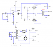
This really confuses me where shall I post it. I got this schematic from a magazine a few years ago here in HKG. I'm planning to build it because the prices of tubes and outputs are lowering a little these days. Does
anyone ever build this amplifier before and or where is it originated?
There are many schematics of tubes driving BJT's and FET's on the web, but this is the other way around. Any comments on it? Shall I
make a regulator for the +/-60V rails, or perhaps a constant current
source for the +60V end. Any suggestion is welcome. Thanks, guys.....
Attachments
The expensive bit of a valve amplifier is the output transformer - closely followed by the HT transformer, rectification and smoothing arrangements. Unless you get really keen, the driver circuitry is comparatively cheap. It's actually possible that providing those +/-60V supplies might make semiconductor drive more expensive than valve drive...
IMO the only advantage is if you require insanely now input noise figures, or your using a power tranny with a nice winding suitable for such. They seem to have been made, since I have one...
I know next to nothing about valve amp design but that posted schematic looks almost too simple to work - can anyone see any problems with it? The design LOOKS alright to me, but it almost looks like an oversimplified circuit to explain amp concepts or something. It looks tempting to build but my intuition says that it would oscillate or blow up or something 😀
bigwill,
I copied this schematic by hand drawing at first, I've lost the original magazine. I think they tranlated that article from an European magazine, because they used to do this in Hong Kong. I remember the article includes a PCB layout, so I'm quite sure it works.
I copied this schematic by hand drawing at first, I've lost the original magazine. I think they tranlated that article from an European magazine, because they used to do this in Hong Kong. I remember the article includes a PCB layout, so I'm quite sure it works.
No, Bigwill has a point, there is no bias supply or cathode bias shown for the output tubes so in fact as drawn it won't work. Otherwise the design is workable, but having heard something quite similar I question the wisdom of building it at all. There are better designs out there.
Bigwill, your intuition is correct. It will blow up. There is nothing to limit the current in the output valves. If the 330k resistors were removed and the 220nF capacitors replaced by short circuits, then the -30V on the collectors would be about right to bias the valves but it would be a bit precarious.
The Circuit
I really made a terrible and careless mistake when drawing the circuit. Here is the correct one. The tubes are biased by the collectors of the MPSA92's at -30V. That's why I am thinking of a regualtor for +/-60V rails thus the bias can be trimmed.
I really made a terrible and careless mistake when drawing the circuit. Here is the correct one. The tubes are biased by the collectors of the MPSA92's at -30V. That's why I am thinking of a regualtor for +/-60V rails thus the bias can be trimmed.
Attachments
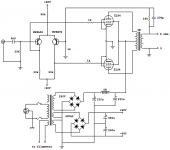
You don't need a +60V regulator, but a -60V regulator and replacing the 30k emitter resistor with an adjustable CCS feeding the wiper of a 100R variable resistor connected between the emitters would be a good thing.
EC8010
Thanks a lot for your good suggestion. Would it be good to ground the tubes through a 10 ohm resistor each so I can easily monitor their current and adjust them after a period of time (months)?
Thanks a lot for your good suggestion. Would it be good to ground the tubes through a 10 ohm resistor each so I can easily monitor their current and adjust them after a period of time (months)?
A 10 ohm current sampling resistor in the cathodes of each output tube is a good idea.
Despite what has been said unless the screens are also operated from a regulated supply, regulating the -60V supply is not such a good idea as every small shift in B+ will result in an attendent shift in operating point. When both are unregulated variations in B+ will be somewhat offset by a similar offset in the bias voltage, while not perfect a lot of the op drift will be cancelled this way.
You can also regulate the B+ in which case you should also regulate the -60V supply.
Incidentally I believe this circuit has almost no headroom beyond what is required to drive the output tubes, and would recommend something like - 70V to -80V supply voltage. The positive supply does not have to be regulated, and with a CCS in the tail you could comfortably get away with about a 12V rail here.
Better still take a look at some of the all tube designs out there on the net. I have heard the AMC hybrid, and at least one home brew of a circuit very similar to this one, and it lacked many of the virtues of good tube sound. The output and power transformers are the biggest % of the cost and would not differ significantly if you choose an all tube design, or even designed one yourself. That pair of transistors could be replaced by a single 6SL7 or even 6SN7 if you wanted something really simple, and don't need lots of gain.
I'd echo everything kevinkr has said. Regulation could actually make the output stage's DC conditions less stable. A single transistor CCS isn't really up to snuff, a cascode would be better. Even then, there's precious little headroom and I see no virtues in this silicon drive.
- Status
- Not open for further replies.
- Home
- Amplifiers
- Tubes / Valves
- Tubes driven by BJT's