Hello everyone,
I have a question, but I need to provide a rather lengthy introduction before stating it.
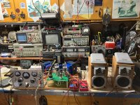
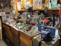
I haven't been active on the forum for a long time since I built my first SSE: the Mancave version. As life has slowed down for me lately, I've found enough free time to work on some projects I started about 10 years ago—an SSE to replace the current amp in my main system (almost done) and a full-blown steampunk mancave SSE version (all the weird parts are sourced, and the PCB is done; it just needs an enclosure and final assembly). I will post more details on both later. I thought these two would be my final builds, but I realized I have another enclosure and enough parts to build one more SSE before I exit the hobby.
My previous and in-progress builds have all of the options plus an ability to gradually adjust the output tube bias via either a precision pot or a switchable resistor matrix. They also feature a 100 mA meters between R17/R27 and the common bus to monitor the cathode current. For what would be my final build, I've decided to take a "minimalistic" (in my understanding) approach, with the amp operating in just two modes: triode with no CFB biased for EL34, or ultralinear with CFB biased for 6550/KT-88 selected via a single switch. However, I still want to be able to monitor the cathode current, mainly to spot a bad or failing tube.
Here is my question: would it be okay to connect R17 AND R27 to the same pole of a single 200-300 mA meter, and the other pole to the common (i.e., inserting about a 2 ohm or less single load between both cathode resistors and the common bus)? Or is this a bad idea, and would I be better off using separate meters for each channel?
Thank you to those who read this post all the way through. I'd appreciate your thoughts.
I have a question, but I need to provide a rather lengthy introduction before stating it.
I haven't been active on the forum for a long time since I built my first SSE: the Mancave version. As life has slowed down for me lately, I've found enough free time to work on some projects I started about 10 years ago—an SSE to replace the current amp in my main system (almost done) and a full-blown steampunk mancave SSE version (all the weird parts are sourced, and the PCB is done; it just needs an enclosure and final assembly). I will post more details on both later. I thought these two would be my final builds, but I realized I have another enclosure and enough parts to build one more SSE before I exit the hobby.
My previous and in-progress builds have all of the options plus an ability to gradually adjust the output tube bias via either a precision pot or a switchable resistor matrix. They also feature a 100 mA meters between R17/R27 and the common bus to monitor the cathode current. For what would be my final build, I've decided to take a "minimalistic" (in my understanding) approach, with the amp operating in just two modes: triode with no CFB biased for EL34, or ultralinear with CFB biased for 6550/KT-88 selected via a single switch. However, I still want to be able to monitor the cathode current, mainly to spot a bad or failing tube.
Here is my question: would it be okay to connect R17 AND R27 to the same pole of a single 200-300 mA meter, and the other pole to the common (i.e., inserting about a 2 ohm or less single load between both cathode resistors and the common bus)? Or is this a bad idea, and would I be better off using separate meters for each channel?
Thank you to those who read this post all the way through. I'd appreciate your thoughts.
Attachments
If you are only using one meter use a shunt resistor in series with each cathode resistor, and then measure voltage drop across the shunt to get the cathode current. A 10 ohm shunt and 0 - 1 volt meter will measure 0-100 ma cathode current if my arithmetic is correct (I = V/R).
Use a DPDT switch with the meter at the common points of the switch.
A 1/4 or 1/2 watt resistor should be fine.
Win W5JAG
Use a DPDT switch with the meter at the common points of the switch.
A 1/4 or 1/2 watt resistor should be fine.
Win W5JAG
Thank you for the suggestion, I appreciate it.
My other builds have an adjustable bias and separate meters on each channel. This amp will have a fixed bias, and the only purpose of the meter would be to detect an abnormal rise in the combined cathode current if/when something goes wrong. So, I’m considering using a single meter permanently connected between both channel cathode resistors and ground to measure the combined draw. This way, if I’m running EL84s and the meter shows over 100 mA, I would know that something isn’t right.
So, the question is: Is this okay to do?
I don't see why it wouldn't be ok, except that if the meter goes open your amp goes dead in both channels.
You could put it in the B+ lead and also pick up the current from the 12AT7.
Win W5JAG
You could put it in the B+ lead and also pick up the current from the 12AT7.
Win W5JAG