could anyone please comment on the question I asked in my last post?
I would say that you have measured and adjusted the idle current fully right.
The bass response is better to measure.
The amount of idle current do not effect frequency response, not at least audible amount.
The rest is up to the 'cook'
Best,
Old post, but you're still an active member, so I will try. I've got a Priboi sitting on my bench, and noticed a few things.
1. The output tube curves look quite non linear.
2. Stock, the frequency response extends to -3dB at 120kHz.. this doesn't seem like a good thing to me!
3. The driver looks badly engineered - way too much gain.
4. Not enough voltage on the 6N6P driver tube... checking the curves it appears to be operating in a fairly nonlinear region.
I listened to it, and I think it isn't working to its potential. It makes lots of power, and doesn't distort or anything, but lacks the transparency of a good tube amp.
The rest is up to the cook above, is an interesting statement - do you know of any solutions to this "problem"?
I am thinking maybe a Dynaco type circuit, using a much higher voltage on the phase inverter, and abandon the second gain stage?
A mullard circuit would seem good too, but if I do that, I can't use the same board.
Any feedback would be interesting.
I was looking at the Marantz 8 circuit for inspiration... similar tubes, oh so much better design!
Last edited:
...and again,"the tank in a tuxedo" 😉
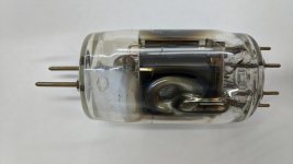
Just got a Priboj amp on my workbench.Uses the initial 6R3S-1 (6P3C-1) output tubes,one of them went south and burned it's cathode 10Ohm/2W Russian metal film (not sure why the fuse didn't react first but this is another story).
Question:is there a specific reason for using 10 Ohm (and reading hundreds of mV across it) instead of a (classic) 1 Ohm resistor?
It seems that I cannot find any 10Ohms/2W having acceptable tolerance (say, 5% or less) but I have some 1Ohm/2W in the 1-2% precision range.
TIA!
Attachments
Sorin Cristea,
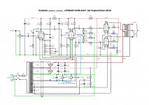
Your schematic shows:
The output tube grids, g1, each have over 128.5k Ohms to ground.
1k grid stopper, 120k, with one path through 30k to ground; and the other path from the 1k and 120k resistor is through 10k/2 potentiometer to another 10k/2 potentiometer to ground (10k to ground).
30k in parallel with 10k to ground (7.5k).
1k, 120k, 7.5k = 128.5k total g1 to ground.
Many RF tubes that are used with Fixed Bias, have low maximum resistance ratings from g1 to ground.
I bet one of your output tubes went into thermal run-away, because of the 128.5k g1 to ground.
The similar 329B tube has maximum g1 grid resistance to ground of 12.5k, 15k, and 100k depending on the application.
To high of a g1 resistance to ground . . .
The tube gets hot, starts to draw g1 grid current (gassy tube, or hot tube), that current changes the g1 voltage, the new g1 voltage causes the tube to draw more g2 screen and plate currents, the tube gets hotter, and runs away, blowing the cathode resistor.
Even though self bias is not recommended for those kind of tubes in RF applications, this audio application might work more reliably with self bias (self bias cathode resistor and parallel bypass cap from the cathode to ground).
You would loose a little output power, but gain a lot of reliability and tube life.
Last edited:
...
Question:is there a specific reason for using 10 Ohm (and reading hundreds of mV across it) instead of a (classic) 1 Ohm resistor?
It seems that I cannot find any 10Ohms/2W having acceptable tolerance (say, 5% or less) but I have some 1Ohm/2W in the 1-2% precision range.
TIA!
I think it boils down to making the measurement of the voltage drop with sufficient precision to infer the cathode current. if it was 35ma, then the voltage drop on 10R is 350mV, whereas with 1R it is 35mV. The precision of the resistor is therefore irrelevant if you can only measure 0.035V to, say, 2 decimal places of precision.
Plus, if you change it, and someone less competent than you is working on the amplifier in the future, maybe they could be caught out?
If you have a bunch or 10R resistors, can you measure them and select the ones closest to 10R?
...and you'd won 🙂 (see pic)I bet one of your output tubes went into thermal run-away, because of the 128.5k g1 to ground.
In the meantime,I took out the fuse (common for both output tubes' cathodes) on that channel...it's a 4A,instead of 0,4A as indicated in the schematic. 😱 Clearly,another idiot who misreplaced that part.
About the "too high g1 res. to gnd" ,thank you very much for the valuable hints.It looks that I'll have to do my math and reconfigure the entire output stage as to make this amp functional and stable.
Yes,that was about it.Your assumption is right,you never know who's gonna work on it and not paying attention at the detail.Thank you!I think it boils down to making the measurement of the voltage drop with sufficient precision to infer the cathode current.
Plus, if you change it, and someone less competent than you is working on the amplifier in the future, maybe they could be caught out?
Attachments
- Home
- Amplifiers
- Tubes / Valves
- tube upgrade benefits, worth the money? 6R3S-1, EF86