Each stage inverts the signal....I had to go back to basic triode theory to confirm that but yes, increasing grid voltage does lower plate voltage.... how easily I can forget! I am back to playing with my preamp breadboard, and want to find out if split loading isn't just an additional B+ dropping resistor and a smaller load resistor...or is it? Will see.... Thanks again!
... want to find out if split loading isn't just an additional B+ dropping resistor and a smaller load resistor.... Thanks again!
Whether a resistor is part of the plate load or for B+ dropping just depends on how it is positioned relative to the B+ smoothing cap. You can regard the B+ at the smoothing cap as a constant DC voltage (approximately) so any resistor between the +ve of that cap and the plate is part of the plate load and any resistor between the +ve of that cap and the previous cap. in the smoothing chain is a dropper.
find out if split loading isn't just an additional B+ dropping resistor and a smaller load resistor...or is it?
If there were a capacitor from the two resistors to ground, and the coupling cap coming directly off the plate, then that would be the case.
The way it is used in most guitar amps is like a volume pot that is permanently stuck in one position. With two equal value resistors, and the signal for the next stage coming from the junction of the two resistors, it's at roughly half volume. (6 dB loss)
Complex amps like the Soldano SLO100 use LDR's to switch in bypass caps, different resistors, and even add extra gain stages. I found the schematics on the web. It takes a careful analysis to understand what's going on there.
Each stage inverts the signal....I had to go back to basic triode theory to confirm that but yes, increasing grid voltage does lower plate voltage
Note, this is only the case in a common cathode amp stage. (90% of guitar amp stages). Cathode followers (used fairly often) and grounded grid stages (ultra rare in a guitar amp) do not invert.
Thanks, I was hoping that was the case. Both resistors then affect the gain, but act as a voltage divider ("stuck pot") for the signal to the next part of the amp.
Yes. The 'stuck pot' in a split plate load is kind of 'upside down' compared to usual. To get more attenuation of the signal to the following stage, the resistor connected to the B+ has to be reduced relative to the resistor connected to the plate.
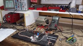
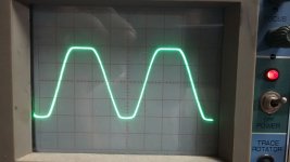
OK, finally got my preamp up and running... basic Fender, 2 gain stages (12AX7), two 100K load R's, and two 2500R 5W pots on the cathodes. 1Meg vol pot between stages. Set cathode R's at 1500R, input 400Hz, vol at max, raised input to 175mV, got first clipping on V2 (2nd stg). V1 still clean. Input raised to 360mV, get first clipping on V1, good clip on V2 (see pic). Then increased cathode R's to 2500R, and clip went away. I think I was making the grid(s) more negative, and moving closer to the sweet spot(s) on the tube data graph... But I wanted to see clipping on the bottom of the sine wave! Do I need more cathode resistance? Larger plate load (say 220K)? I'm gonna try both (cathode R first). Not using any bypass caps, they only affect frequency response (right?). Tubelab is right, this may take a while... (and I am searching for that elusive "stretched" sine wave...).
Attachments
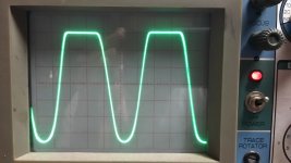
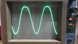
Finally was able to induce clipping on either top or bottom of the sine wave, using a 12AU7, a lot more input (1000mV), and 3500 ohms on the cathode to play with. Got the top to clip with 3500R 1st stage and 0.0R 2nd stage, and the bottom with the reverse: 0.0R 1st stage and 3500R 2nd stage... Was no clipping on the signal from the 1st stage, it was all 2nd stage (makes sense, the 12AU7 is a very low mu tube}. Done playing for the night!
Attachments
Looking at the waveforms in post #27, the left-hand one will have a lot of even harmonics, while the right-hand one will have more odd harmonics. If you listed to the output on a speaker you might be able to hear the difference.
(Might be easier to hear the difference at a lower frequency like 200Hz.)
(Might be easier to hear the difference at a lower frequency like 200Hz.)
In the right-hand waveform in post #26, notice how the top of the wave is broader than the bottom, yet it's still close to a sine-wave. To me that is an important part of the 'tube sound', the distortion is very mild and the player would still regard the sound as 'clean' but with subtle additional (mainly even) harmonics that we like to hear.
The 'solid-state' police will no doubt jump on me, but I don't think you will get that from a transistor.
The 'solid-state' police will no doubt jump on me, but I don't think you will get that from a transistor.
As a member of the "solid-state police" I am sure you can produce similar effect without any tube - if you want so. After many private investigations I prefer a perfect symmetrical distortion that comes in softly - something you cannot expect from a single ended amp.
^This. You merely need a clipping diode with series resistor. Only run to mild clipping.
And in my experience, that much distortion in signal is very easy to detect. It's not a modern sustained "high gain" tone, but at that point the tone is anything but "clean".
Try that as clipping effect "as is" and you'll probably find out it sounds more like a radio station off tune than a complete "tube amp". It will also sound very "bland" because the harmonic structure of clipping remains static: The harmonic distortion products will not alter or change, only their magnitude will in relation to magnitude of overdrive. It's not a very exciting nor "touch sensitive" effect. There's so much more in the process of generating good overdrive tone than just the clipping process.
Last edited:
and I am searching for that elusive "stretched" sine wave...
You get that from gain compression inherent to triode common cathode amps: When plate voltage approaches B+ stage's voltage gain decreases. It results to that kind of "soft clipping" type compression, unless you ovedrive things enough to hard clip the signal at plates of course.
Transistors do the very same thing when you misbias them. With the drawback of losing some device gain, you also get very similar performance by introducing another diode in parallel with transistor's emitter diode junction.
Last edited:
A solid-state diode follows a physical law in which the current depends on the exponential of the voltage. A thermionic (vacuum tube) diode follows a law in which the current depends on the voltage to the power (3/2).
I think I was making the grid(s) more negative, and moving closer to the sweet spot(s) on the tube data graph... But I wanted to see clipping on the bottom of the sine wave! Do I need more cathode resistance? Larger plate load (say 220K)?
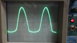
Think about those curves i showed you earlier. By increasing your cathode resistor, you're effectively giving the grid more of a negative bias. I'm guessing with the photo on the left, the (pos) half of the wave is hitting or approaching positive grid and clipping. You've got more room before saturation on the bottom so by applying a more negative grid voltage, you shift the whole input waveform towards the bottom and the top half of your signal is no longer in that range.
That I agree with...a more negative grid moves the output signal UP (output is inverted). I want to (with the right pot, and enough signal) move the output up and down, and see clipping on the top then bottom, taking measurements to confirm what tube data predicts...
- Status
- Not open for further replies.
- Home
- Live Sound
- Instruments and Amps
- Tube triode preamp design, a quest for Headroom....