I've got a few clone builds under my belt, a Champ, Princeton and Bassman, and looking now at the Marshall 18W, with so many variants in preamps, I need to go back to basics, to understand what they all are trying to accomplish.... So, armed with data sheets, DMMs and a scope, I'm putting a 2-stage 9-pin socket on my breadboard, with variable EVERYTHING, to see what gives me headroom, hot/cold bias, freq response, input sensitivity/tolerance, etc. Split load plate, grounded cathode, hi/low B+, you name it. Any thoughts on any interesting design features that might teach me more about how the twin triode works? Thanks!
Sounds like a fun project. When you vary things such as using a different value cap somewhere, it's quite difficult to appreciate the difference in the sound if you have to power off, drain caps, do some tack soldering, warm back up again, and retest (after 5 minutes). So my suggestion is to build in some switches here and there, where possible, so that you can toggle between two trial component values and instantly hear the difference, see it on your scope, etc.
A switch or two is a great idea, but I want to make only one change at a time (with a switch for sure) to know what change is doing what. I will switch out the B+, so the caps there will be isolated when I swap parts. Thanks!
The best device for this is a decade box for caps and resistors. You can switch many values in a short period of time. Tack in the largest resistor you anticipate will sound good and parallel other values on for decreasing increments. Same for caps except start with the smallest value you think will sound good and parallel on others for increasing values. No soldering required except for final installation of the value you like best for your build.
Even if you don't have a decade box, this system works well to eliminate soldering.
Even if you don't have a decade box, this system works well to eliminate soldering.
A decade box would be a no-brainer, if I had one... Na, just going to tack a couple components at a time in on one end, and use half a clip lead (soldered onto the other end) to "hot swap" back & forth. Won't even have to power it down, no OT to worry about, just a load resistor after the de-coupling cap. Hey, another value to vary - load impedance! Won't look pretty, but will give me what I want.
Oh, and I will put 2 100K pots on the plate, so I can split the load while having up to 200K total plate load to B+...
Finally started testing, having put together a basic 2 stg preamp, one tube (12AU7), with B+ adjusted for 80 vdc on plates, 100K loads, 1500R cathode. Measured gain, then swapped in a 12AX7....was surprised to see voltages go up, and gain of course.. Noting that (per tube data sheets) the plate R for the AX7 is roughly ten times that of the AU7, I'm a bit surprised. I know tubes are not passive components, but doesn't lower voltages mean you're loading down down the supply with more current draw? I've just started, and I already know I've got a lot to learn....
Hi Guys
If the quest is for highest headroom as the thread name suggests, then you should follow the advice in TUT and set the plate voltage to be just around half of the supply voltage - actually a tad higher than this. This will centre the signal in the available "window" between cutoff and saturation and provide the best clean sustain possible.
Have fun
Best way to understand what is going on is to print out the plate characteristics of 12AX7 and 12AU7, draw load lines and find your bias points.
At a risk of over-simplifying: a 12AU7 draws more plate current than a 12AX7, but it also needs a bigger negative Vgk bias voltage to stop it drawing plate current.
When you put in the AX7 you get less plate current, so less voltage drop across the plate load resistor, and hence plate voltage closer to B+ voltage.
Just to add a little: Guitarists have got into the habit of substituting different types from the 12A?7 series into circuits designed for a particular type (e.g. putting a 12AU7 into a circuit that was designed for a 12AX7). In general it's fun and doesn't usually do any harm (except that plate load resistors can get a bit more current, and heat, than the original designer intended).
However, it is strictly speaking 'the wrong way round'. Designers selected a tube type first and then designed the circuit to suit that type!
However, it is strictly speaking 'the wrong way round'. Designers selected a tube type first and then designed the circuit to suit that type!
Last edited:
Malcomb-so with less current you get more gain? No wonder the AX7 is popular! What am I missing? Higher voltage + less current = still more gain than a AU7?
Struth-but doesn't the cathode bias you set (+ or -) move you around this window? You would want to center it there as well? I do like the "1/2 plate/B+ voltage" suggestion, thanks!
Struth-but doesn't the cathode bias you set (+ or -) move you around this window? You would want to center it there as well? I do like the "1/2 plate/B+ voltage" suggestion, thanks!
Last edited:
... -so with less current you get more gain? No wonder the AX7 is popular! What am I missing? Higher voltage + less current = still more gain than a AU7?
Struth-but doesn't the cathode bias you set (+ or -) move you around this window? You would want to center it there as well? I do like the "1/2 plate/B+ voltage" suggestion, thanks!
Well, yes, there's a lot of things going on here.
Gain is 'change in output voltage'/'change in input voltage'.
A triode, in the usual configuration, has a plate current which varies according to the (input) grid-to-cathode voltage Vgk. The plate load resistor turns plate current variation into an output voltage variation.
If you bias Vgk in the middle, between 'cut-off' and 'Vgk=0' the input signal can swing equally positive or negative (either side of Vg=0) before clipping.
When you are looking at tube circuits you have to get into a mind set of looking at (a) DC or quiescent conditions - which is about DC voltages and currents, and (b) AC or signal conditions - which is about how those voltages and currents vary over time, with the signal.
You can see all these things much more clearly with a load line and bias point on the plate characteristics, than you can describe them in words!
The Valve Wizard
is recommended.
Last edited:
Hi Guys
RCA and other tube manufacturers of the day published tables of typical values at two or three standard voltage levels for many of the voltage amplifying tubes. You can have the same gain at low current and at higher current with most of the tubes and generally get the highest gain with higher supply voltage.
TUT shows a table of a model triode stage operated at different voltages with different Rk and Ra values, and the resulting idle currents and voltage gains., These were actually measured results of a test bench circuit - you are just repeating this test.
If you have a scope, you can adjust Rk and set the plate signal so that it clips at the same time on the top and bottom for a given stage. This is the maximum sustain idle point. Do this test with the load connected that the stage will drive in the real circuit or there will be asymmetric clipping in the latter.
With cascaded stages, you MUST pad the signal between stages as the grid cannot handle the full plate output of the preceding stage. Proper design indicates the use of grid-stops even with interstage attenuation.
You might optimise the circuit for a given 12A_7 but there is no problem whatsoever of swapping in any other member and just going with it. This is a part of the "tone creation" business of guitar amps.
Note that 12A_7 -family has an open-circuit voltage rating of 540V, so using supplies up to 500V is safe. The 300V rating you see is based on using an inductive load and takes into account the flyback voltage in such use.
Have fun
Thanks to you both. Darn if I'm not learning something here! Yes I am reading Valve Wizard's chapter on triodes as I play with this preamp, I found out I needed a grid leak resistor between stages (forgot it, got no signal, tube wouldn't conduct), and he confirms the Golden Rule about plate/valve resistance. And you bet I'm using my scope-I've seen clipping on top, bottom or both, on my clone builds, learned about hot & cold biasing, and am learning now about how they affect headroom. Back to the breadboad.... 🙂
Malcomb-so with less current you get more gain? No wonder the AX7 is popular! What am I missing? Higher voltage + less current = still more gain than a AU7?
Struth-but doesn't the cathode bias you set (+ or -) move you around this window? You would want to center it there as well? I do like the "1/2 plate/B+ voltage" suggestion, thanks!
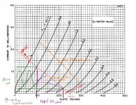
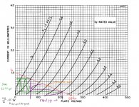
As some have explained a bit already, its dependent on your curves. Quick example I drummed up. First case has a bit less gain than the second due to the lower plate resistor, letting it flow more current. So for a corresponding 2V P-P swing on your grid voltage, the steeper curve will present less output swing, albeit more linear operation.
Looking then at the same time at a 12AU7 graph at the same conditions, you can get a considerably LARGER swing in the input voltage. Additionally however, the gain will be lower. The reason why you can stick an AU in an AX circuit and have it work but give you less overall gain with more headroom.
This is how I've come to understand it, i guess if that's incorrect I'd appreciate someone smacking me along the head 😛
Attachments
Last edited:
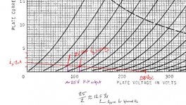
Thanks for the marked up graphs! It really shows the difference in headroom in the two tubes, for the same input swing. I've read it, but the graphs makes it easier to understand when you can see it. Also where the center point for grid bias should be, unless you want to get hot or cold bias clipping (I think?).
to see what gives me headroom........If the quest is for highest headroom as the thread name suggests
Headroom.....closely related to dynamic range, although technically headroom only refers to achieving louder louds, without sacrificing too much in the quiet department.
Many great guitar players have a pedal board as big as a small table and they can control everything from the tone to the looper with their feet. These guys need an amp with tons of headroom since most of the tone and volume stuff is done on the pedal board.
Ever wonder how the guy that has a guitar cord running from his guitar to his amp can make his tone go from squeaky clean to sweet creamy distortion without touching his amp, or how he rips off a lead run and some of the notes are clean, yet some are distorted, all while both hands are busy playing the guitar? During all of this the average volume coming out of the amp stays relatively constant........Lack of headroom, AKA touch sensitivity.
Touch sensitivity is not an easy thing to get right. There are several ways to get there, each with somewhat different results.
The old style amps with a single volume control distorted when turned up loud enough. This was primarily clipping in the power amp stage, and if driven hard enough the output tubes produced some rather intense distortion with lots of higher order harmonics.
Marshall and others added the presence control to tame some of the higher order nastiness. Then came the master volume control. With this you could use a guitar with hot pickups, an overdrive pedal, or an extra gain stage in the preamp, to get some distortion out of the preamp while running the power amp clean, OR play with the settings such that the preamp begins to compress as the power amp just starts to clip. Now the guitar's volume control plays a big part in the amp's tone, since a little more drive can push two stages into distortion at the same time.
This has been taken to its fullest extreme in some modern amp designs. This is why you found the "split load resistors" in the plate of one of the triodes. Without the voltage divider, the following stage would be pushed into hard clipping by the excessive gain of the preceding stage, hence some gain is thrown away.
You can set up every stage in the entire amp to be just on the edge of clipping, such that a little harder picking, or a nudge of the guitars volume control will send the amp into distortion. It is a matter of personal preference as to which stages distort first, and how hard. This depends a lot on the tubes, how they are biased, the speakers, the guitar, and how it is played.
When you are exploring tube circuits, and what "knob" causes distortion, it is good to have a speaker, a scope, and a computer sound card with FFT software, all hooked up so that you can see and hear what types of distortion you like, and what sounds ugly.
In the HiFi world, amp techs test everything at 1 KHz. This is not a common fundamental note in a guitar, so I prefer to use about 200 Hz. Again this is a matter of personal preference, and again it depends on the guitar and how it is played, and the speakers used.
Hard clipping gets ugly fast because of the higher order harmonics. This is worse with bright sounding speakers. Hard clipping brings on a bunch of IMD distortion meaning it is usually only useful for lead (single note at a time) or power chords (notes chosen such that the IMD products are benign or musically related).
Look for distortion where the sine wave gets stretched vertically, yet remains rounded. This is predominately second harmonic, which sounds nice. It is easy to achieve with a starved pentode, or two triodes chained and set up so the clipping is gentle and asymmetrical. The second stage gently clips the other side such that the to stages generate a symmetrical stretching. This is what the "split load" was for.
As you are about to find out, you can spend days....no weeks, tweaking parts in search of "tone."
Awesome info and history Tubelab! I've been distracted recently with a Peavey hybrid amp I picked up cheap, been looking at the SS preamp, but want to plug a tube preamp into the effects return, for full tube effect. And your suggestion to try assymetrical distortion with two stages (bias one hot, the other cold?) sounds very tempting. Will be trying just that soon. I use my scope as much as my DMM, but will look into FFT (for distortion analysis?). And your point about the importance of the guitar in the equation I agree doesn't get the attention it deserves. We guitarists are more than signal generators! Thanks.
with two stages (bias one hot, the other cold?)
No, you bias them the same. Each stage inverts the signal, so the second stage works on the other half of the signal.
Usually running a tube too cold allows the plate voltage to rise causing the top of the waveform to be abruptly clipped off as the signal runs into the B+ rail. This effect is abrupt, and creates some higher order harmonics. Smaller coupling and bypass cap values accentuate this effect, while larger ones can mellow it somewhat.
Too much current lowers the plate voltage causing the tube to reach saturation when driven hard. Tube saturation is usually gradual, and tube dependent. The overall effect on two stages is a fattening of the sine wave.
Music, and especially a heavily hammered guitar, is not a sine wave, so the sounds you hear and see while performing static sine wave testing don't always translate well into real transient laden guitar playing. Again, there is a lot to learn by building something and playing with it. Every guitar player is different too. I tend to beat the crap out of a Strat or Les Paul style guitar......
I built a lot of Champ based simple tube amps when my daughter was in the high school band, taught music, and had musical friends over a lot. I once made a Champ style amp that used a pair of 6 X 9 inch JBL car speakers that I took out of my car before trading it in. No one liked that amp, it didn't ROCK, so it became the practice amp for the Roland keyboard in the music room. One day a kid came over with his ES-335. He plugged into that amp and declared that it was the sound he had been searching for. It did sound nice, so I gave it to him.
but will look into FFT (for distortion analysis?).
The FFT will give you a representation of the level of EACH harmonic. It will allow you to learn what harmonics sound good, and which ones suck (5th and 7th). It lets you see how two notes intermingle (IMD distortion) when they go through the same distorted chain.
Last edited:
- Status
- Not open for further replies.
- Home
- Live Sound
- Instruments and Amps
- Tube triode preamp design, a quest for Headroom....