


Felipe,
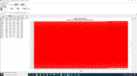
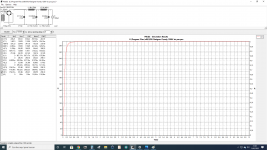
The "first bump" only shows the circuit "charging".
The real test is loading the output with repetitive current pulses.
The "first bump" only shows the circuit "charging".
The real test is loading the output with repetitive current pulses.
Bela I use PSUDII not LTSpice, but thanks for the info. If 1st cap 12uF, 2nd 220uF & 3rd 40uF he can get 5mV of ripple, also become fast without ringing.
Attachments
Last edited:
Thanks Bela - I'll try that. Anything else that would dampen the ringing more? I have DC Link 12uF and 30uF or 40uF. Plus some 68uF Kemet electolytics.
If you chaining CL modules the ringing always occurs. Selecting proper values of components may damping it.
In my opinion the output of you PSU is over filtered.... if it is the "power" output.
3mVpp hum range is the preamp or phono territory.
The VC2 point (CLC: 308V 58mVpp) is rather the "real" amplifier power supply output.
If you want to test PSU, the load must be same as the "real", power amplifier stage current (steady current+peek current) on "power" output, and the VAS and driver stage current on "driver" output.
If this is the real case, the original PSU component values are OK.
Last edited:
Thanks Bela. Yes - this is the PSU for the 2a3/6C4C output stage. This has the book values, 250v, 60mA, -45v. So the PSU supplies 120mA at around 310v.
So what would you suggest as a "lighter" PSU? Leave the 2 chokes and use smaller caps....... something else?
I use a Mac and need to activate the download of PSUD. I don't have LT Spice.
I'd welcome all suggestions, especially a model that tests good using the components I have (or others). The 100K resistor is to discharge the capacitors fairly quickly. I always put that in for safety. It doesn't have to be after the second capacitor, but that's where I've seen it placed most often.
Try to use PSU as I sketched in #127:
12uF-8H-40uF for power tubes, 1H-12uF for another tubes.
If the hum too much for output tubes, try to increasing both capacitor in the first chain: -first- 12uF and 40uF. The 1:3 ratio is recommended.
12uF-8H-40uF for power tubes, 1H-12uF for another tubes.
If the hum too much for output tubes, try to increasing both capacitor in the first chain: -first- 12uF and 40uF. The 1:3 ratio is recommended.
PSUD2 will indicate the same 50Hz ringing on an output voltage waveform due to a step load change as seen in post #121. Perhaps a little easier to simulate in PSUD2 if someone is new to simulating power supply behaviour.
Sag refers to the fact that a class B push pull amplifier will cause the HT voltage to drop (sag) on music peaks if you have a tube rectifier based HT supply. So if you have an amp with a tube rectifier it will have sag. You may well interpret this effect on the music as fuller, more rounded and smoother but it is caused by sag whether you want it or not.Thanks. I don't think I want sag, though, I want smoothness.
Cheers
Ian
Not all tube rectifiers exhibit noticeable sag - the 5V4 with a choke input filter has negligible sag from about 20mA out to 175mA.
If you chaining CL modules the ringing always occurs. Selecting proper values of components may damping it.
In my opinion the output of you PSU is over filtered.... if it is the "power" output.
3mVpp hum range is the preamp or phono territory.
The VC2 point (CLC: 308V 58mVpp) is rather the "real" amplifier power supply output.
If you want to test PSU, the load must be same as the "real", power amplifier stage current (steady current+peek current) on "power" output, and the VAS and driver stage current on "driver" output.
If this is the real case, the original PSU component values are OK.
View attachment 1024551
View attachment 1024552
Now makes sense the 100K bleeder resistor to discharge C1 & C2 caps.
You'd put like 100R in series with each diode. Adjust R for desired "sag"...
In each anode?
RECT. DCV drop
5U4-GA 33V
5U4-GB 35V
5U4-G 35V
According the DCV drop you only have to use a resistor to sag the desired voltage, use 25W aluminium housed wire-wound power resistors (if possible no inductive).
Last edited:
Try to use PSU as I sketched in #127: 12uF-8H-40uF for power tubes, 1H-12uF for another tubes.
If the hum too much for output tubes, try to increasing both capacitor in the first chain: -first- 12uF and 40uF. The 1:3 ratio is recommended.
Did that. Sounded fine without the second choke. Tell me about the 1:3 ratio. You mean first to second cap, so 10 to 30 for instance? Is this widely known or your personal experiments? Both valid of course.
I'm now preferring the SIC diode power supply to the 5U4 one. Both have only DC Link capacitors.
I've now got to the point where I think the capacitors need some thought. The DC Link caps (Kemet) are smoother and rounder sounding than the Kemet electrolytics. However the electrolytics, though they have more of an edge, seem to have a sharper attack and a little more detail. With some regret I took them all out. So now wondering if I should try any caps other than DC Link Kemets. There are other DC Link caps, for instance, and the Vishay ones I have sound good too, maybe a touch cleaner. I'll have to look at all the PSU capacitor threads, and there are certainly plenty of those.
At some point I'll try bypassing the DC Link caps, so e.g. bypass a 12uF with a 1uF polypropylene. I'm not expecting much or indeed anything from this but I can try it.
Also to simulate better the tube sag by introducing a series inductance after the resistor, inductance from 1mH to 100mH—a 10mH inductor would be a good place to start with a 100 ohm resistor.
You could also put the resistor in the ground leg of the transformer... More than one way to skin a cat 🙂 I'm just carrying over from putting a resistor in each anode lead of a vacuum diode.In each anode?
RECT. DCV drop
5U4-GA 33V
5U4-GB 35V
5U4-G 35V
According the DCV drop you only have to use a resistor to sag the desired voltage, use 25W aluminium housed wire-wound power resistors (if possible no inductive).
View attachment 1024703
Aluminum housed resistors need a heatsink - remember that.
- Home
- Amplifiers
- Tubes / Valves
- Tube rectifier versus 1200v SIC diodes?