This is the second version of my tube preamp but this time has different goal, not to drive headphones but I wanted balanced outputs to drive power amp directly so everything is optimised to drive line-level loads.
Compared to the first version I have significantly upgraded power supply. High voltage part contains CRCRC filter before it goes to the mosfet + LD1086 regulator with lots of blocking and capacities around. Thanks to this I have basically battery-like psu for the tubes with excellent mains filtering.
For tube filaments I have LM337/317 balanced psu with again lots of filtering around and slow turn-on.
There is also regulated 5V1 psu for relays and controll of the preamp + to power raspberry pi board with DAC ES9038Q hat for wifi audio streaming.
Audio path / voodoo improvements over 1st version:
There is my own "invention/evolution" design of combined voltage and current feedback directly into input differential pair. Thanks to this, preamp has excellent stability, transient response and low distortion. Thats why its somehow VFA/CFA preamp, I have tried this in previous samples also with WCF output (white cathode follower) for unbalanced version with even better results of 0,0002% THD into 300R load 😎
Audio extras
- audio part of PCB is standalone so its possible to wire it via IDC ribbon cable to whatever control board, I have designed two versions:
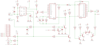
Analog "pure" one with 555+4060+4040 timers
Digital with attiny with IR remote control
Preamp schematic:
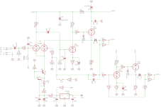
PSU
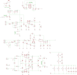
I/O
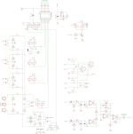
Control ("analog" without remote) // edit // actually I noticed one change in schematic, that I have not used T2, as that would send (audiodetect) reset loop all over the place from analog to digital gnd, so I have replaced this one with cny17f opto to have this competely clean and separated. Digi gnd is complately isolated from analog gnd, and only one way where they meet is from DAC RPI hat into analog input. By doing so there is absolutely pure connection without any mess in harmonics...
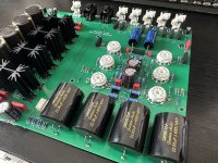
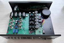
Some build pics
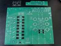
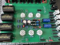
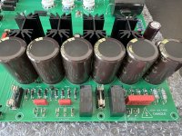
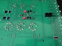
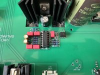
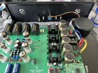
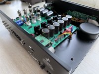
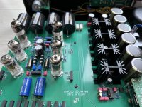
Mechanical design
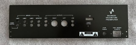
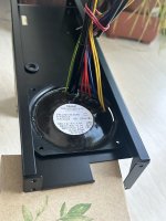
I wanted to design future-proof sturdy enclosure with complete access to PCB from both sides... The main structure consists of separated rear panel (for easier label printing), 8mm thick machined anodised aluminium front panel, and to interconnect panels there is C-shaped profile on side which creates base for PCB and on other side U-shaped tunnel with the very same function but to also hold transformer and to cover all the wiring inside of it:
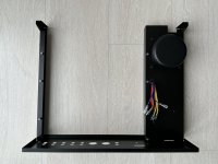
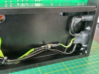
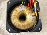
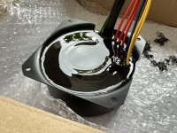
For absolute best mains filtering I have used custom audio-grade toroidal transformer with earthed primary/secondary copper shielding. Transformer windings are shielded on the outside by several layers of laminations. I potted whole assembly into iron cover with polyuretane potting compound. So as a result transformer is tripple shielded. Toroidal iron cover is actually hanging in the U-shaped tunnel by rubber vibration dempeners, so its also mechanically isolated from the rest of the chassis and "levitating".
Aand as upload sucks and cannot insert more images and when i do so on external server i get hated i will continue in next post🤔
Compared to the first version I have significantly upgraded power supply. High voltage part contains CRCRC filter before it goes to the mosfet + LD1086 regulator with lots of blocking and capacities around. Thanks to this I have basically battery-like psu for the tubes with excellent mains filtering.
For tube filaments I have LM337/317 balanced psu with again lots of filtering around and slow turn-on.
There is also regulated 5V1 psu for relays and controll of the preamp + to power raspberry pi board with DAC ES9038Q hat for wifi audio streaming.
Audio path / voodoo improvements over 1st version:
- in signal path there is minimum coupling capacitors and if so all are audio-grade polypropylenes
- I wanted to minimise series relay connection as much as possible, so there is only one reed-relay at the input selection, for the output mute I choosed relay to short to the ground so there is no signal going thru the contact.
- All impedances are lower also in feedback loop
- I have improved current sinks in input differential pair = TL431 + low noise BC550, soldered from the back of the pcb to even smaller thermal drift and improved stability
There is my own "invention/evolution" design of combined voltage and current feedback directly into input differential pair. Thanks to this, preamp has excellent stability, transient response and low distortion. Thats why its somehow VFA/CFA preamp, I have tried this in previous samples also with WCF output (white cathode follower) for unbalanced version with even better results of 0,0002% THD into 300R load 😎
Audio extras
- audio part of PCB is standalone so its possible to wire it via IDC ribbon cable to whatever control board, I have designed two versions:
Analog "pure" one with 555+4060+4040 timers
Digital with attiny with IR remote control
- there is automatic power-off function after 30minutes without audio signal to save electricity and tube life.
- stereo/mono switch
- preamp gain switch
- (tape)monitor switch
- hardware mute switch
- as mentioned in psu section above, one of the inputs is RPI with DAC hat for dlna audio streaming thru wifi
- first line input contains also remote-out +5V trigger so its possible to turn on phono preamp with selecting the one
Preamp schematic:

PSU

I/O

Control ("analog" without remote) // edit // actually I noticed one change in schematic, that I have not used T2, as that would send (audiodetect) reset loop all over the place from analog to digital gnd, so I have replaced this one with cny17f opto to have this competely clean and separated. Digi gnd is complately isolated from analog gnd, and only one way where they meet is from DAC RPI hat into analog input. By doing so there is absolutely pure connection without any mess in harmonics...

Some build pics


Mechanical design
I wanted to design future-proof sturdy enclosure with complete access to PCB from both sides... The main structure consists of separated rear panel (for easier label printing), 8mm thick machined anodised aluminium front panel, and to interconnect panels there is C-shaped profile on side which creates base for PCB and on other side U-shaped tunnel with the very same function but to also hold transformer and to cover all the wiring inside of it:


For absolute best mains filtering I have used custom audio-grade toroidal transformer with earthed primary/secondary copper shielding. Transformer windings are shielded on the outside by several layers of laminations. I potted whole assembly into iron cover with polyuretane potting compound. So as a result transformer is tripple shielded. Toroidal iron cover is actually hanging in the U-shaped tunnel by rubber vibration dempeners, so its also mechanically isolated from the rest of the chassis and "levitating".


Aand as upload sucks and cannot insert more images and when i do so on external server i get hated i will continue in next post🤔
Last edited:
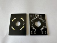
Below are more pics of pot wiring, ir sensor installation and backlight of knobs. I also did jumper on control board to be able to switch between cold white (modern) and yellow(vintage) knob backlight as I have many different power amps 🙂
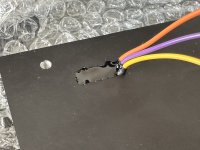
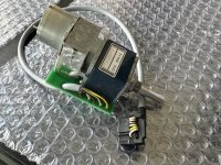
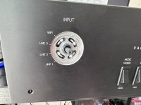
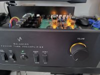
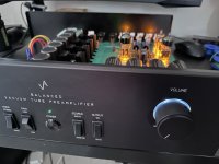

Finished preamp
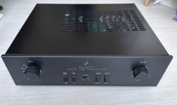
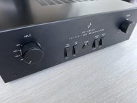
Some video what it does...
notice the "pop" when I mute, not sure why it does this, as previous version did not - but one thing is different and thats the muting relay is shorting output to the ground (via 100R resistor). Maybe some leftover DC of big caps or changing feedback loop impedance by shorting the output or what, I suppose that's the tax for not going with signal thru relay contacts 🙄 voodoo hiend **** or what 🤔
Some measurement below, 2k load, spectrum calibrated to dBV... please see mains harmonics 😎


Finished preamp


Some video what it does...
notice the "pop" when I mute, not sure why it does this, as previous version did not - but one thing is different and thats the muting relay is shorting output to the ground (via 100R resistor). Maybe some leftover DC of big caps or changing feedback loop impedance by shorting the output or what, I suppose that's the tax for not going with signal thru relay contacts 🙄 voodoo hiend **** or what 🤔
Some measurement below, 2k load, spectrum calibrated to dBV... please see mains harmonics 😎
Last edited:
Wiliks,
Looks good, performs good, nice job!
Because my latest tube amplifiers are balanced low power amplifiers, I can only use them with my XLR output CD player.
I should build a single ended to balanced preamp, so I can also use my balanced amplifiers with my LPs, FM tuner, DVD, and TV.
If I do design and build a single ended to balanced preamp, I am sure it will be simple and not all that good looking.
after a bit of debugging why I had a pop when switching the modes I was thinking it has to be something about DC potential differences. Today when I was digging in I have found out one of the Jantzen output caps was probably defective and was getting 0,3-0,5VDC on its output. After replacement to different cap all the noisefloor went significantly down as well as distortion, also no more pops and bangs when switching the modes 🤯
I think no more Jantzen caps for me anymore in future 🙁 could be bad lack, but anyway... 👎
below new measurements... 0dBV:

-6dBV a bit regulated volume

I think no more Jantzen caps for me anymore in future 🙁 could be bad lack, but anyway... 👎
below new measurements... 0dBV:
-6dBV a bit regulated volume
Your way of creating an inverted signal to the other polarity reminds me of ARC's way in their early power amps and some preamps during Bill Johnson's era. Have you thought of using a concertina/cathodyne/split-load approach before arriving at your design?
ofc I thought, and also tested... basically I already have differential input stage so could continue with going like that to make split phases you are right, however it comes with several drawbacks compared to my approach...
The current feedback here is the key for very low noise and distortion + overall stability. By this approach I have excellent unbalanced preamp, and whenever balanced signal is needed its just simple inverting buffer added in the chain.
- by doing so, I would need to loop negative feedback from/to both polarities to make proper compensation, meaning it would require shade feedback on the input and so to make reasonable low input noise it would need to have low input impedance
- it would have much higher overall distortion
- I would not be able to implement my current feedback diff solution
The current feedback here is the key for very low noise and distortion + overall stability. By this approach I have excellent unbalanced preamp, and whenever balanced signal is needed its just simple inverting buffer added in the chain.
Oo that looks similar indeed 🤔 Maybe even better as they direct dc coupled second stage to the diff amp, also the way how they “regulate” amout of feedback comming from the follower, interesting idea.
My first how i come with this was using it with white cathode follower in headphone amp, where I had exactly half of the anode voltage at the output. As half of the unused input diff stage was just tied to psu via resistor there, i was thinking how to get better coupling in diff… by just bringing unused half directly to psu would result in very unbalanced current so as middle point of wcf was exactly at voltage I needed I tried to connect it there, and by regulating current in cathode ccs of diff, I align second half to very same voltage and current as first. Tried the very same here but with basic cathode follower and works same 🙂
Basically current flowing thru follower feeds half of the diff stage as well, as current changes in follower, the diff follows that and change in its current creates further feedback in diff. As this is directly coupled there is no resistor, no capacitor nothing to mess the phase, it strongly contrubutes to excellent stability. Has its limits ofc, but works like a charm in terms of noise and thd
forgot to post an update about this one ...
as I was unable to measure so low distortion figures and preamp was designed for basic line-level loads I had to tweak my cosmos adc. I've replaced one XLR input as straight and designed a small pcb containing parallel opa1612 buffer fitted directly on the pins. Input of cosmos is in mono mode and I have switch on the case and can switch between buffered or direct input. By doing this I was able to reach -133dB thd readings in "loopback" which is I suppose way beyond design limit of this adc and the opa capabilities... with 10k input (and this is expected load for this tube preamp to feed power amp)

New preamp measurements are below: 0dBV

and as preamp is supossed to be actually amplifying, also 10dBV output measured below.

(these are all unbalanced outputs measured, in balanced mode it distorts more in range of 0,00x because of lower olg)
as I was unable to measure so low distortion figures and preamp was designed for basic line-level loads I had to tweak my cosmos adc. I've replaced one XLR input as straight and designed a small pcb containing parallel opa1612 buffer fitted directly on the pins. Input of cosmos is in mono mode and I have switch on the case and can switch between buffered or direct input. By doing this I was able to reach -133dB thd readings in "loopback" which is I suppose way beyond design limit of this adc and the opa capabilities... with 10k input (and this is expected load for this tube preamp to feed power amp)
New preamp measurements are below: 0dBV
and as preamp is supossed to be actually amplifying, also 10dBV output measured below.
(these are all unbalanced outputs measured, in balanced mode it distorts more in range of 0,00x because of lower olg)
Your balanced circuit prompted me to look into alternative ways to have balanced output with feedback for both polarities. I'm also looking for a more "symmetrical" circuit. I stumbled into another ARC circuit that allows either SE or BAL input and with balanced output. It uses differential input but the wrinkle here is that the second long-tail pair is used as feedback entry point with the plates tied together so fb is through the plates instead of the cathodes typically. I do think the 3rd LTP is not necessary as the feedback can be feed back to the second tube without flipping the phase, provided all parts values recalculated of course. It also provides better headroom for the input tubes. This way the whole circuit for stereo requires only 6 tubes, just like yours. Have a look.
I stumbled into another ARC circuit
ARC are certainly not my fav audio company, but even they eventually figured out nfb in a tube line stage is a pointless dead end. And they achieved this last century.
- Home
- Amplifiers
- Tubes / Valves
- Tube preamp with balanced outputs (cfa+vfa)