It just occurred to me.
Yes, the 100k input resistance of the volume control/power amp will load down the cathode follower at AC, but what does this have to do with the DC conditions of the cathode follower? There's a big honkin' 3.3uF cap blocking DC from the load.
Or maybe I'm missing something...
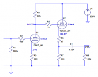
Here's a CCDA using a 12AU7 with 22k load resistors (attached).
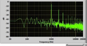
Spice says the THD at 1V RMS out will be 0.9%, almost entirely 2nd harmonic.
Yes, the 100k input resistance of the volume control/power amp will load down the cathode follower at AC, but what does this have to do with the DC conditions of the cathode follower? There's a big honkin' 3.3uF cap blocking DC from the load.
Or maybe I'm missing something...
Here's a CCDA using a 12AU7 with 22k load resistors (attached).
Spice says the THD at 1V RMS out will be 0.9%, almost entirely 2nd harmonic.
Attachments

Last edited:
Missing a diode (or a Ne-bulb) as usual.Or do you like 300V between grid and cathode of U2 at start-up ? Yes, only an example, but never the less, often forgotten.
Mona
Mona
Missing a diode (or a Ne-bulb) as usual.Or do you like 300V between grid and cathode of U2 at start-up ? Yes, only an example, but never the less, often forgotten.
Mona
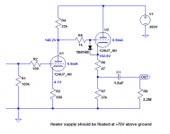
Agreed, and good catch. Yes, should put a 1N4148 between grid and cathode of U2. Cathode of diode goes to tube's cathode. Also, the heater supply should be lifted about +75V.
hi
just read your stuff and learn, thanks all
for now i play with the simulator and build the CCDA.
my DAC have DC output, its problem? i connected it to the preamp and no different, i suppose its because the cap.
do i have to put bypass cap before the preamp?
thanks
just read your stuff and learn, thanks all
for now i play with the simulator and build the CCDA.
my DAC have DC output, its problem? i connected it to the preamp and no different, i suppose its because the cap.
do i have to put bypass cap before the preamp?
thanks
You suprised me. I didn't think you were going to actually build it; I thought we were still in the discussion phase.
Interesting that you don't hear a difference between the two. Does the 12AU7 deliver enough gain? I usually like my normal, full listening volume to happen with the volume control at about 11 o'clock on the dial, or maybe 12 o'clock. That way there's a wide variety of 'quiet' levels available between 8 o'clock to 10 o'clock on the dial, and loud levels 'look' loud on the dial.
In that schematic, R8 should be 1M to 2.2M instead of 100k. (The 100k value was to simulate your F5's input impedance while running the Spice simulation.) Since your F5 amp has a 100k input impedance, the load resistor on the line amp only needs to make sure there's always a load on the cathode follower even if it's not connected to anything, to protect it.
Definitely put a 1N4148 diode between the grid and cathode of U2. The banded end (cathode) of the diode should go to the cathode of the tube. Your heater supply should be lifted to about +75V.
Also, C1 can be reduced to 1uF with no ill effects. It's easier (and cheaper) to find a really good 1uF 300VDC rated capacitor than a 3.3uF part of equal quality.
How far off are the voltages in the actual circuit from those in the schematic?
--
Attachments
Last edited:
Hi
Just quick build, even no socket 😱
I think the gain is ~10, I don’t have POT, straight from the DAC 0.2v and to the 12au7, from there I connected it to buffer (B1) and to F5, I try to change the R8.
I don’t have this diode, so for now its without. (i have 1N4005)
My heater is not lifted (afraid to burn again), so its float 6.3vdc PS.
C1 is wima mkp10 400v 2.2uf
I didn't measure the voltage, I do it today, just play music with it.
Can you help me with the comparison? There is something I need to feel difference between the 12au/x except the gain?
thanks
my PS is 222vdc
Attachments

Last edited:
Holy breadboard, Batman! 😱
To add more gain, put a 330uF or 470uF capacitor in parallel with R3. That should bring the gain up to about 15X.
There were studies suggesting that we don't hear 2nd harmonic distortion as easily as higher and odd order distortions (5th, 7th, etc.). Since these simple triode circuits make predominantly 2nd order harmonic distortion, the difference between the 0.1% predicted for 12AX7 and the 0.9% predicted for 12AU7 may not be noticeable to you in this context. That's what I found interesting about your comment.
If you were to rig up something like this using an opamp, I wonder if that would sound appreciably different...
The reason for the diode is that the grid of the cathode follower (U2) will shoot up to the full B+ (300V) at turn on, while the cathode will be at around ground potential (0V), until the tube warms up and begins conducting. This 300V difference between grid and cathode can strip pieces of the cathode off during that time when the tube is not yet conducting.
The reason for lifting the heater supply to +75V is that with the cathode of U2 at +150V, that exceeds the maximum cathode-heater voltage of 100V by some 50V. That also can cause cathode stripping. If you float the heater supply to +75V, the cathode of U1 is -75V below the heater, and the cathode of U2 is +75V above the heater. That way they're both within that 100V limit.
--
Last edited:
my PS is 222vdc
Unfortunately, that still doesn't fix the floating heater supply issue. You'll still need to float it. The limit is 100VDC from heater to cathode.
And you'll still need that diode (grid to cathode of U2). I think you can use your 1N4005 there. It's not the best choice of diode, but it will work (safely).
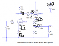
The lower B+ destroys the 'constant current draw' part of the CCDA. Oh well. Just change R3 to 560 ohms.
--
PS - I entered those SPICE distortion predictions wrong. They should be 0.1% for the 12AX7 version and 0.19% for the 12AU7 version.
Last edited:
The B+ has no significant effect on the constant current operation; the external load does.The lower B+ destroys the 'constant current draw' part of the CCDA. Oh well. Just change R3 to 560 ohms.
Thanks for weighing in, although I'm not sure I understand. The external load is a First Watt F5 amplifier, which has an input impedance of 100k ohms. That, in parallel with R8 (2.2M), will make for a 95.7k ohm load on the output.
Is the driving impedance the 1/gm output impedance of the cathode follower (about 500 ohms) in parallel with the load resistance (95.7k)? That would be 497 ohms, or hardly changed from the cathode follower output impedance unloaded.
Am I looking at this the wrong way?
--
Is the driving impedance the 1/gm output impedance of the cathode follower (about 500 ohms) in parallel with the load resistance (95.7k)? That would be 497 ohms, or hardly changed from the cathode follower output impedance unloaded.
Am I looking at this the wrong way?
--
Constant current operation is acheived when the cathode follower drives the same AC load impedance as the first gain stage.* In this case they are both driving 22k. Any external load appears in parallel with the 22k cathode resistor, so it unbalances the circuit. However, I wouldn't worry about constant current operation. It's nice if you can get it, but most people don't, and nobody seems to mind!
*Technically the cathode follower's load needs to be a bit smaller since its gain is less than unity, but this is usually ignored.
*Technically the cathode follower's load needs to be a bit smaller since its gain is less than unity, but this is usually ignored.

- Status
- Not open for further replies.
- Home
- Amplifiers
- Tubes / Valves
- Tube preamp 30 gain design with 12ax7