Hi
My goal is to build tube preamp that amplify the signal from the DAC (0.1v) to my power F5 amplifier (2-3v)
I read about many design for that propose, but can't decide what best for me:
Love sweet sound with 2th harmonic, need *30 gain, I have 250-300vdc, 12ax7, 6n2p-ev, 12au7.
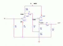
I start to build the scheme in the picture, its sound very good. I hope that I explain it correct, I hear in the voice of the singer little distortion, what is it?
I don’t have pot in the input: 50mv*50=2.5v -> power amp
Appreciate another design suggestion.
thanks
My goal is to build tube preamp that amplify the signal from the DAC (0.1v) to my power F5 amplifier (2-3v)
I read about many design for that propose, but can't decide what best for me:
Love sweet sound with 2th harmonic, need *30 gain, I have 250-300vdc, 12ax7, 6n2p-ev, 12au7.
I start to build the scheme in the picture, its sound very good. I hope that I explain it correct, I hear in the voice of the singer little distortion, what is it?
I don’t have pot in the input: 50mv*50=2.5v -> power amp
Appreciate another design suggestion.
thanks
Attachments
Last edited:
With one gain stage you will only get a gain of around 11.
You need a gain of around 20.
The cathode follower final stage has no gain.
Add another gain stage.
You need a gain of around 20.
The cathode follower final stage has no gain.
Add another gain stage.
I threw the circuit into LTspice and ran a simulation. LTspice predicts about 48x gain. That would be what you'd expect from a 12AX7.
The cathode follower doesn't have any gain, but the first stage common-cathode 12AX7 certainly has gain.
Grid stoppers are important to keep oscillations from occurring, especially for the cathode follower.
The grid bias on the cathode follower is only -0.5V. The cathode follower is likely working with some grid current due to contact potential.
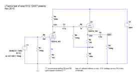
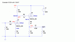
I've attached a schematic with voltages predicted by LTspice. Can you check your circuit's voltages and see if they match what LTspice has predicted?
You might want to take a look at John Broskie's articles on the CCDA circuit:
CCDA: constant-current-draw amplifier
--
The cathode follower doesn't have any gain, but the first stage common-cathode 12AX7 certainly has gain.
Grid stoppers are important to keep oscillations from occurring, especially for the cathode follower.
The grid bias on the cathode follower is only -0.5V. The cathode follower is likely working with some grid current due to contact potential.
I've attached a schematic with voltages predicted by LTspice. Can you check your circuit's voltages and see if they match what LTspice has predicted?
You might want to take a look at John Broskie's articles on the CCDA circuit:
CCDA: constant-current-draw amplifier
--
Attachments
Last edited:
Oops. I made a mistake. It seems in the original circuit, the grid bias on the cathode follower is about -1V, not -0.5V as I erroneously stated. That should be OK, but some of your 12AX7s might be drawing grid current. Maybe, maybe not.
For what it's worth, I ran the circuit through LTspice again and it predicts 0.064% THD at 1V RMS output into a 10k ohm load. Gain of about 45x.
The difference from the first time through is that I ran the simulation into a 1M ohm load the first time, but 10k this time. 10k is a much tougher load...
--
PS - FirstWatt F5 amp's input impedance is 100k ohm, according to the F5 manual.
Last edited:
Like this? Other half of tubes for the other chanel.Hi
My goal is to build tube preamp that amplify the signal from the DAC (0.1v) to my power F5 amplifier (2-3v)
I read about many design for that propose, but can't decide what best for me:
Love sweet sound with 2th harmonic, need *30 gain, I have 250-300vdc, 12ax7, 6n2p-ev, 12au7.
I start to build the scheme in the picture, its sound very good. I hope that I explain it correct, I hear in the voice of the singer little distortion, what is it?
I don’t have pot in the input: 50mv*50=2.5v -> power amp
Appreciate another design suggestion.
thanks
Mona
Attachments
Looking at the F5 manual, it shows that its voltage gain is about 15dB, or about 5x. The input sensitivity (voltage in necessary to clip output) is not stated.
What is the input sensitivity of an F5 amp? (How much input signal is needed to reach full power output?)
--
What is the input sensitivity of an F5 amp? (How much input signal is needed to reach full power output?)
--
hi
yes my gain now is about *45.
the F5 power amp work well with 2-3v of signal. The load, F5, is 100k so i don’t care about the tube output impedance.
rongon: thanks for the simulation, appreciate if you can upload the file that i can play with it.
Ketje: thanks for the suggestion, in the article John Broskie's recommended extra cathode resistor (increases the cathode follower’s linearity, but at the cost of increased output impedance) in my case it’s needed, no?
The CCDA look very promising, read this article, very interesting and it follow me to the Aikido line stage, so CCDA or Aikido line stage?
i have 8*6n2pev, 3*12ax7, 1*12au7, so i don’t care to use 2 tube for channel if it improve the sound Q. need to learn more about this two design.
Think I start to build the Aikido line stage with 2*6n2p-ev
Attachments

If you want gain of 30x, an ECC88, 6DJ8 or Russian 6N23P would be good.
6N1P would also be good for this.
6N1P would also be good for this.
“Thanks for all the suggestions guys.
How is CCDA different from "Aikido" and has anyone tried both and compared them?
Aikido uses a second tube in an arrangement that allows a nulling of power supply noise.
I have listened to both and prefer the CCDA as it seems to have a bit more lively sound and used two less tubes.. I used the PS1 regulated supply for both circuits.
You will be very happy with your selection.”
So the CCDA more sweet from the Aikido, and more noise, I try the CCDA first with 12ax7
Sorry guys, but I don’t understand, there is no big different between the first scheme that I build and the CCDA, (except Grid stoppers), so just add Grid stoppers to my current scheme?
There is change in the SQ between the circuit? (CCDA, first scheme)
thanks
There is change in the SQ between the circuit? (CCDA, first scheme)
thanks
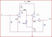
If you use degenerative feedback in the input stage you can adjust gain from less than 1 to <µ with Rx. This could give some nice distortion figures at least in a low gain configuration.
Attachments
Last edited:
Sorry guys, but I don’t understand, there is no big different between the first scheme that I build and the CCDA, (except Grid stoppers), so just add Grid stoppers to my current scheme?
There is change in the SQ between the circuit? (CCDA, first scheme)
thanks
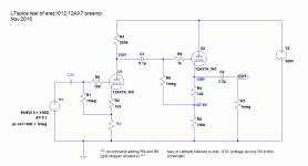
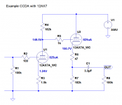
The CCDA is basically the same as your circuit, except that the first tube's plate and the second (cathode follower) tube's grid have to be at 1/2 of the B+.
In your schematic, R10 and R12 are different values. In the CCDA, they would be the exact same value. With B+ of 300V, the plate of the 1st 12AX7 should be at just about 150V, and the cathode of the 2nd 12AX7 should be just about at 150V too. By necessity, both 12AX7 triodes will be drawing the same plate current.
The idea behind this is that the two triodes will 'see' any power supply noise 180 degrees out of phase from the other, so the noise will cancel out at the output. This reduction in noise at the output is supposed to sound better.
I've attached an example CCDA circuit using 12AX7. Note that the plate of U1 and the cathode of U2 are both at right around 150V, and that the plate currents of both U1 and U2 are identical (0.825mA each).
--
Attachments
You got ripple from the power supply (r0). A fraction of this ripple (r1) is fed into the CF and then to the output (r2).The idea behind this is that the two triodes will 'see' any power supply noise 180 degrees out of phase from the other, so the noise will cancel out at the output.
Where is the ripple cancelation?
Attachments
Yeah, I misunderstood it. No ripple cancellation. Just enforced constant-current operation so that power supply impedance effects are minimized.
According to John Broskie in Tube CAD Journal (CCDA: constant-current-draw amplifier):
Both the grounded-cathode amplifier and the cathode follower are in voltage phase, but not current phase. For example when the grounded-cathode amplifier sees a positive going input signal, its plate current increases, which increases the voltage developed across the plate resistor, which in turn swings the plate voltage down.
This downward swing is then relayed into the cathode follower's grid, whose cathode follows its grid, reducing the voltage across the cathode follower’s cathode resistor, which in turn causes the cathode follower to decrease its current conduction to the same degree that the previous stage's current increased, as they share the same load resistance. Thus, the net current draw from both stages remains unchanged, although the cathodes and plates might be swinging hugely.
...the current draw varies with the signal. Now if the power supply presents a resistance, or worse an impedance -- in other words a frequency-dependent resistance -- then the input signal will be superimposed on the B+ voltage, frequency skewed and phase-shifted, where it will feed back into the first and second stages. Now, doesn’t a constant-current-draw operation by a line amplifier make more sense? Of course, if a perfect power supply were used, then both the constant-current-draw and the non-constant-current-draw line-stage amplifier would perform equally well.
All that to say that the power supply current draw is in equal amplitude but opposite phase, so current draw from the power supply cancels out. The power supply doesn't have to work as hard, so super-low power supply impedance isn't a necessity for good performance. Not Aikido by any means, just a sort of baby step in that direction.
--
Last edited:
You have to take the external load into account. The current through the load might ruin this balance.This downward swing is then relayed into the cathode follower's grid, whose cathode follows its grid, reducing the voltage across the cathode follower’s cathode resistor, which in turn causes the cathode follower to decrease its current conduction to the same degree that the previous stage's current increased, as they share the same load resistance. Thus, the net current draw from both stages remains unchanged, although the cathodes and plates might be swinging hugely.
You have to take the external load into account. The current through the load might ruin this balance.
Can you provide an example of where this might happen in a real-life application? I'm honestly curious. I was thinking if you use this CCDA circuit as a driver for a single-ended power amp, then it might have to drive signal into a grid that's drawing current because of output tube overload. Any other examples?
--
Look no further than your own circuit.. no grid current is needed to throw the balance off. CCDA relies on both triodes having equal load values. On your example, R4 is equal to R7. If these resistors remain as the only loads, total amount of AC current flowing to both load is approximately constant at any time. However, you have introduced 100k as R8. This is effectively in parallel with the cathode follower's 182k, making it equal to a load of 64k. AC current flowing to this load will not be equal to the one going to R4. If you draw the loadline, things will be clear. Current draw difference will be the most at the extreme points of voltage swing.
To make your circuit draw approximately constant current, R8 should be >> R7. Preferable 10x or more. This would make R7//R8 close to R7.
To make your circuit draw approximately constant current, R8 should be >> R7. Preferable 10x or more. This would make R7//R8 close to R7.
Can you provide an example of where this might happen in a real-life application? I'm honestly curious. I was thinking if you use this CCDA circuit as a driver for a single-ended power amp, then it might have to drive signal into a grid that's drawing current because of output tube overload. Any other examples?
--
Not sure if entirely correct, the bottom freq. response is improved if load current is included in the balance equation under heavy load.
Attachments


Last edited:
I understand, thanks.
The problem is not so much with the circuit as with the 12AX7. The major drawback of a device with that high of an internal impedance (70k ohms or thereabouts) is that it can easily be loaded down by the load presented by the succeeding device (the device that it is amplifying signal into). I made R8 100k to simulate the typical input impedance of a tube power amp, or the highest value usually chosen for a volume control. (The original schematic had 1M, which when put in parallel with the input impedance of a real-life power amp or volume control is going to come down in value by quite a lot.)
If I were designing something to do this job, I would not use a 12AX7. Actually, with only 20x to 30x gain required, a 6DJ8 or 6N6P would be better.
Of course, if you want to do it correctly, you could use a CCS plate load to make the input a mu-follower, and from there into a mosfet source follower so that nothing can upset the loading on the amplifying device.
Or use a CCDA made from 6N6P triodes with 10k load resistors (R4 and R7) run at 15mA plate current per triode. The ra of the 6N6P's would then be only about 2k ohms -- only 5% of the 100k load. A 6N6P would not be overly upset by a 100k ohm or 47k ohm load, as would be commonly encountered in the real world.
If designing for a solid state amp with 10k input impedance, then you'd have to take further measures. The mosfet follower would become almost mandatory. Maybe a pair of triode-wired EL86's would do the trick. They'd eat up more current than a 6N6P, of course. Actually, all of these other choices eat up orders of magnitude more current than a 12AX7!
Unfortunately, the OP did not mention something with really low ra as one of the tubes available for this project.
Of these, 12AU7 is the best choice, but its ra is usually 8k to 10k, depending on operating point chosen. Harmonic distortion will also be much higher. But perhaps that would be a 'good' thing.
--
The problem is not so much with the circuit as with the 12AX7. The major drawback of a device with that high of an internal impedance (70k ohms or thereabouts) is that it can easily be loaded down by the load presented by the succeeding device (the device that it is amplifying signal into). I made R8 100k to simulate the typical input impedance of a tube power amp, or the highest value usually chosen for a volume control. (The original schematic had 1M, which when put in parallel with the input impedance of a real-life power amp or volume control is going to come down in value by quite a lot.)
If I were designing something to do this job, I would not use a 12AX7. Actually, with only 20x to 30x gain required, a 6DJ8 or 6N6P would be better.
Of course, if you want to do it correctly, you could use a CCS plate load to make the input a mu-follower, and from there into a mosfet source follower so that nothing can upset the loading on the amplifying device.
Or use a CCDA made from 6N6P triodes with 10k load resistors (R4 and R7) run at 15mA plate current per triode. The ra of the 6N6P's would then be only about 2k ohms -- only 5% of the 100k load. A 6N6P would not be overly upset by a 100k ohm or 47k ohm load, as would be commonly encountered in the real world.
If designing for a solid state amp with 10k input impedance, then you'd have to take further measures. The mosfet follower would become almost mandatory. Maybe a pair of triode-wired EL86's would do the trick. They'd eat up more current than a 6N6P, of course. Actually, all of these other choices eat up orders of magnitude more current than a 12AX7!
Unfortunately, the OP did not mention something with really low ra as one of the tubes available for this project.
need *30 gain, I have 250-300vdc, 12ax7, 6n2p-ev, 12au7.
Of these, 12AU7 is the best choice, but its ra is usually 8k to 10k, depending on operating point chosen. Harmonic distortion will also be much higher. But perhaps that would be a 'good' thing.
Love sweet sound with 2th harmonic,
--
Last edited:
- Status
- Not open for further replies.
- Home
- Amplifiers
- Tubes / Valves
- Tube preamp 30 gain design with 12ax7