i just have purchased an ef184 tube, so cheap on eBay, paid £2.99 including shipping and that's my next step down the line to try,...so many ideas coming already,...Many Thanks to you All for the suggestions 🙂.,
Pick up some 85A2 if you can they are the most stable references tubes can provide, provided you run them at 3-3.5mA
You can run the EF184 quite hard at 10mA but lifetime wont be that good.
PASS tube, you can also try the PL508 if you have it in your junkbox. 17V heater, and run the heater in series with the EF184 you can then power the regulator with 24VAC transformers that are plentifull surplus.
You can run the EF184 quite hard at 10mA but lifetime wont be that good.
PASS tube, you can also try the PL508 if you have it in your junkbox. 17V heater, and run the heater in series with the EF184 you can then power the regulator with 24VAC transformers that are plentifull surplus.
Attachments
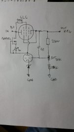
I have tried your suggestion and used 10M45s instead 100k resistor, and took the voltage from the 6l6 anode instead its cathode, the voltage across 10m47s is 7.5v, I have to say that hear no difference in sound against the previous model,You can use an LND150 which has Idss of ~2mA and 9V across it well within the safe-operating-area. Output impedance will be better as well.
Attachments
that looks great, and i will keep it for later, atm experimenting with the original 6l6/12ax7 idea 🙂, many Thanx.Pick up some 85A2 if you can they are the most stable references tubes can provide, provided you run them at 3-3.5mA
You can run the EF184 quite hard at 10mA but lifetime wont be that good.
PASS tube, you can also try the PL508 if you have it in your junkbox. 17V heater, and run the heater in series with the EF184 you can then power the regulator with 24VAC transformers that are plentifull surplus.
There may be no difference in the sound in Case 1, there may be a difference in Case 2, Objectively, lower output impedance is a worthwhile goal.I have tried your suggestion and used 10M45s instead 100k resistor, and took the voltage from the 6l6 anode instead its cathode, the voltage across 10m47s is 7.5v, I have to say that hear no difference in sound against the previous model,
Yes, that's true, ...but I do prefer the sound of case one in fact. ..sometimes it measures better but doesn't sound better 😎.... Objectively, lower output impedance is a worthwhile goal.
Being a high mutual transconductance frame grid pentode, the EF184 serves very well here. And it is cheap. Anmyway, you may also try some pin-compatible alternatives: First, the EF80, it's non frame grid predecessor. Due to it's not as high gm, the outcome might be somewhat inferior, but still sufficient enough. It might be even cheaper than a EF184. Then there are their remote control derivatives EF85 and EF183, the latter one also featuring a frame grid and high gm. By forcing some high cathode current of about 5 to 10 mA, grid g1 to cathode voltage will be kept low enough to ensure sufficient gm.
Anyway, it's reasonable to check the prices before tinkering with alternatives 😉.
Best regards!
Anyway, it's reasonable to check the prices before tinkering with alternatives 😉.
Best regards!
Yes, I have bought an EF184 and I'm waiting for it to be delivered!, I...cant wait to try it 🙂. ...Thank you.Being a high mutual transconductance frame grid pentode, the EF184 serves very well here
hi, i have received ef184 tube, and now am not fully sure how to implement it into my design instead of 12ax7, to make it work and not to mess up anythingBeing a high mutual transconductance frame grid pentode, the EF184 serves very well here. And it is cheap. Anmyway, you may also try some pin-compatible alternatives: First, the EF80, it's non frame grid predecessor. Due to it's not as high gm, the outcome might be somewhat inferior, but still sufficient enough. It might be even cheaper than a EF184. Then there are their remote control derivatives EF85 and EF183, the latter one also featuring a frame grid and high gm. By forcing some high cathode current of about 5 to 10 mA, grid g1 to cathode voltage will be kept low enough to ensure sufficient gm.
Anyway, it's reasonable to check the prices before tinkering with alternatives 😉.
Best regards!
..thanks.
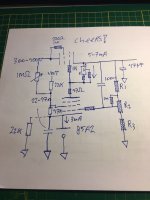
Well you need a divider for the screen grid, thats for sure.
Do you know thevevenin equivalent circuits? Read the datasheet, choose a G2 voltage with respects to cathode, read the current from the datasheet. and calculate two resistors one from regulated out to G2 and one from G2 to cathode.
If you use the inner mu of the tube, you can calculate a divider that will compensate for tube ageing. and you can also use the inner mu to calculate how to inject hum from the unregulated voltage into G2 to get extra ripple rejection at very low cost.
Now the easy way is just to calculate a divider, Your zener is 20V you want the screen grid at 150V with respects to cathode, so you have 130V to drop, cause the G2 is at 170V with respect to ground. screen grid current can be up to 4mA but is normally 2.5mA. Now if we calculate the divider at 4mA through the upper resistor this gives 250x130 which is 25K+7K5 33K for conveinience sake.
Now the other resistor from G2 to the cathode needs to sink 1.5mA at 150V Which is 666*150 or about 100K
Now if you want to inject ripple into G2 from the raw supply, you can use a 1Meg pot, and lower the 100K resistor to 68K. just turn the pot untill you have lowest ripple at 300V out. Due to G2 shifting slightly there WILL be a slight shift in output voltage Circa 1-2V.
However, Ideally you also change the reference from zener diode to gas regulator tube, because you are essentially making a closed loop system, and reference noise is amplified by: (output voltage/reference voltage).
A 85A2 is amazingly low noise reference tube and also very stable if you keep its operating current near 3mA. to do this you calculate G2 divider current plus anode CCS current, and you add a resistor in parallel to the 85A2 to shunt some of the current away from the reference.
Attachments

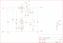
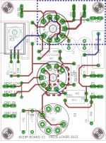
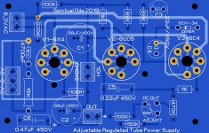
On another Note, I had some spare time, and made another revision of the board posted previously, I added a 10M45S on a little heatsink. And some other parts, kept the mounting holes and socket position the same.
Attachments

- Home
- Amplifiers
- Power Supplies
- tube power regulator