Obviously, but PSRR is supposed to be better with CCS biasing than with a resistor. The -30 didn’t have significant ripple under load, even while the circuit was misbehaving. Looking for AC on the rails is pretty much standard procedure when sorting out misbehavior.
I tried several different tails this AM. The Diff Amp is not driving an audio output stage,I suppose I could voltage double the -30 volt supply and make a -30 for the output stage bias and -60 for the input LTPs to gain some CMRR and just bias the damn things with resistors.
It doesn't need to be balanced. A resistor tail is OK. So I tried both 30V & 150V tails.
The models in EWB for vacuum tubes are 2nd order so they look after the 3/2s thing.
But there is no provision for a conducting diode formed by the grid to cathode potential going +ve.
A SS diode covers that problem on the CF when the signals get large..
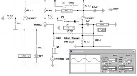
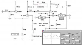
These sims are both driven hard while the scope is DC coupled to the CF,
That way the limits of the output voltage swing can be tested. More later. 🙂
Attachments
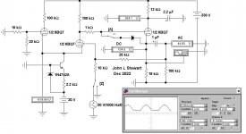
In Op Amp f2 the CF PS is increased to get some improvement.
It doesn't help in an Op Amp to throw away half the gain with the pair of equal plate resistors in the diff amp front end.
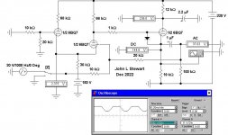
In Op Amp g2 a 100V Zener is stuffed into the plate cct of the unused half of the diff amp.
Could we see a schema of your power supply pls. 🙂
It doesn't help in an Op Amp to throw away half the gain with the pair of equal plate resistors in the diff amp front end.
In Op Amp g2 a 100V Zener is stuffed into the plate cct of the unused half of the diff amp.
Could we see a schema of your power supply pls. 🙂
Attachments
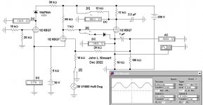
The overall power supply is on the complex side but it works. During this exercise, only the 3 tubes in question are even populated. The power amp section is working, but I’ve pulled the tubes so nothing stupid happens.
The Baxandall circuit (coming next) won’t need the LTP. One would argue that it’s not “needed” in the input buffer either - but the input runs could be 20 feet and the amp and source both with 3 prong plugs. Audio return cannot connect to the chassis at all or I’ll end up with half a watt of 60 Hz hum. Transformer would be “easier”, but the idea was not to spend hundreds of dollars on this, and active balanced was the plan. It should work.
The Baxandall circuit (coming next) won’t need the LTP. One would argue that it’s not “needed” in the input buffer either - but the input runs could be 20 feet and the amp and source both with 3 prong plugs. Audio return cannot connect to the chassis at all or I’ll end up with half a watt of 60 Hz hum. Transformer would be “easier”, but the idea was not to spend hundreds of dollars on this, and active balanced was the plan. It should work.
Attachments

This seems to be true by definition, although the mechanism isn't obvious. This has been a very interesting and mysterious thread. Much thanks to all.Then there is coupling between the channels through the -30V.
What's an easy way to test if the common impedance in the -30VDC supply could cause this issue? Suppose that the impedance were not linear.
All good fortune,
Chris
I would say you CCS could be oscillating at HF. But that's quite surprising unless its all wires. It the voltage on the 2k2 11.3V or it is something different. And does the signal on the plates change when you probe the resistor.
One of the original k2-w tube opamps uses two 12ax7s IIRC, triodes configured as LTP at the front, an amp and then the final acting as a buffer. Only issue is the +/-320V! https://www.researchgate.net/figure...a-Photo-courtesy-of-Joe-Sousa_fig17_238193814
Parasitics do explain a lot of mysterious stuff, so maybe we still need the answer to post #8.
All good fortune,
Chris
All good fortune,
Chris
If so a 1k stopper right on the base of the c3902. You have enough reservoir on the -30V rail I cannot read the value. What does your -30V look like on the scope.
You were on the right track in disconnecting the CF, and running the diff-pair open-loop. Your objective should be to first get one channel's input stage to function correctly open-loop. Completely disconnect the second channel's circuit for now. Power only one channel. Next, ground BOTH the inverting and non-inverting inputs to the powered channel. If the circuit no longer oscillates, apply a test signal to the non-inverting input. If the circuit begins oscillating again, trouble-shoot the circuit in this 'Coupled-Cathode' configuration, which essentially forms a CF stage driving a CG stage, with both stages biased by the same CCS.
My suspicion is that your PS implementation is the culprit. Don't assume that your implementation is accurately following the schematic. Assumptions prevent productive trouble-shooting. As was pointed out upthread, the 60Hz/120Hz frequency of the oscillation tells you that it's somehow power supply related, so the first order of business when trouble-shooting is to make certain that the power-supply is providing clean, correct power to the circuit. Verify this right at the PS side of the anode resistors, not back at the PS itself. Also, measure that the CCS tail supply is correct and clean. If tall of he power supplies are correct and clean, re-make all of the circuit's ground connections. Don't assume they are good simply because they appear to be good to the naked eye.
If the circuit still oscillates with correct, clean power, and good ground connections, there may be some sort of simple hook-up error when you wired the circuit. You may need to retrace each wire to verify that it is correct. Be careful to see what is actually wired, and not what you expect is wired.
Last edited:
It’s a 1000uf on the -30v, with millivolts of hum. The ”oscillation” is line frequency - although it’s amplitude is much higher than mu times the amount seen on the actual supplies. 50 volts peak to peak open loop.
One channel by itself (LTP plus the follower) works perfectly. Connect the second channel and all hell breaks loose. With resistors in the tails instead of the CCS’s it works perfectly (the current is off a bit but could be trimmed). When “all hell breaks loose” the -30V remains stable.
if it is a high frequency oscillation (well beyond scope BW) in the CCS, it would have to be an odd-mode (push pull) phenomenon since it requires both operating before it starts up. The 60 Hz observed may be the HF oscillation cutting in and out at a line frequency rate - could it be the heater circuit that’s pumping it? I’ll have to try RF chokes in the tails. Or maybe a few hundred ohms of R would be enough.
Ill get back to it this evening. Didn’t have a bit of trouble with the power amp LTP, and other than supply voltage and about 2x the current it’s not much different. I could just up the tail voltage and use a resistor, but it would be nice to “fix” this.
If both oscillate then you may end up with some beat. Its highly unlikely but passable. But your on to the highly unlikely and you not a newbie. I would try a 1K in the base of each transistor as its easy. The scope may not go up to those bandwidths. If its oscillation then monitoring the plate signal and moving your finger around the transistor will have a large effect.
Both. And it only starts up when the second channel is connected.
Baudouin - if it’s the kind of oscillation I’m suspecting the only “beating” is the channels against one another. At the actual oscillation frequency, the two collectors would be outphased 180 degrees. Not like two slightly different frequency oscillators - both make a single oscillator.
I do see this sort of thing in RF power amplifiers which employ parallel transistors. GaAs FETs love to do this sort of $*. Build one on an IC where the power transistor stack is a half wavelength *wide and it’s hard NOT to get it to do it.
I am just thinking if you cannot get it to work then give up on amps. Instead add a mixer and build this instread:
http://www.channelroadamps.com/articles/theremin/
http://www.channelroadamps.com/articles/theremin/
Actually in simulation I have A LTP driving another LTP oscillate in simulation although there was no direct feedback path. It only occurred with a CCS and this caused the gain just to go over. The fix was to place a capacitor from plate to plate of the LTP so it started to roll off at around 50KHz. This fixed it. Maybe this is what's happening. Sometimes the miller effect can have roll to play.
I reason I ask, is because the preamp schematic appears to show different treatments of the power supply feed between the two channels. Also, the PS schematic is a bit confusing in it's own right.
First, the preamp schematic. It shows that one channel receives 330V directly from the power supply, while the not shown channel receives the same 330 volts only after passing a 12K & 22uF RC isolation filter. Perhaps, both channels' feeds receive such RC filtering, but that's not what's shown. I would try bypassing the 12K resistor(s) to see if that makes the oscillation go away. If it does, then either the 12K resistor is too high, or the 22uF capacitor is too low, or the fact that one channel has an additional RC supply filter while the other doesn't, is somehow causing the oscillation. Most suspect of all is that the CF of the one channel is modulating the supply to the diff-pair of the other channel via the RC filter.
The power supply schematic, meanwhile, shows two 330 volt source-follower regulated supply feeds. One is labeled 'preamp', while the other appears to be labeled 'front-end'. It's not clear whether the one labeled front-end is also powering the preamp circuit in some manner, or is referring to some outside front-end that's elsewhere. I suspect, it's the latter, but that's not perfectly clear.
Last edited:
Just the followers share the 12k and cap. It is just to drop the plate voltage, since this will raise gm (Lower the Z out) and drop unnecessary dissipation. The two 330V regulators are for the preamp circuits and power amp front ends. Only one was used to power this. The other ran the gain stage and LTP splitter for the power amp, which was working properly. The only stability problems there were the usual loop stability issues, tuned in by cleaning up the square wave response. The “gotcha” was the hard-wired 475k G1 resistors to allow phase-swapping without much rewiring, the driven side needed a bypass so it saw a lower driving point impedance. All of that falls into the more or less “normal” category for stability issues. I didn’t have to chase down ghosts.
Attachments
Did anyone say bypass all the PS leads with a 0.1 microF disc ceramic cap on short leads to common at the LOAD?
Seems obvious, but I ask anyway.🙂
Seems obvious, but I ask anyway.🙂
I would suspect cathode-heater, ccs issues.
Rise the heater above cathode potential to reduce leakage.
Replace the ccs with a resistor.
The above should be easy to implement, just to make sure...
I remember, Philips adviced, with some smallsignal tubes, to keep Rk below 20k.
I remember also, that Philips did not always stick to that.
Pete
Rise the heater above cathode potential to reduce leakage.
Replace the ccs with a resistor.
The above should be easy to implement, just to make sure...
I remember, Philips adviced, with some smallsignal tubes, to keep Rk below 20k.
I remember also, that Philips did not always stick to that.
Pete
Last edited:
- Home
- Amplifiers
- Tubes / Valves
- Tube op-amp WTF