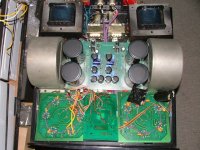
Its a dual channel in a single chassis amplifier. 3 pairs of parallel P-P EL-34 with output of 200W. Toroidal power transformer which was burnt together killed the separate drivers circuitry power supply. Its only on one of the channel. I made the rewind of all the power transformers and it works, but, with high hum, but the other channel dead quiet. I think the cause was the bias meter on the front was misleading making the setting too high that set off the imbalance of the power tubes which had several resistor burnt also replaced. But the hums no way to get rid of...
and also the middle bias control board is made with IC control which I think is malfunctioning because the actual measured current and the shown one is different, although the pots are still able to control. Thanks your help...
and also the middle bias control board is made with IC control which I think is malfunctioning because the actual measured current and the shown one is different, although the pots are still able to control. Thanks your help...
hum usually means some bad grounding or bad caps... those could easily have been fried.
IC controlled bias is beyond my ken...
dave
IC controlled bias is beyond my ken...
dave
Hi,
Just guessing but it could be a calibrating resistor or a protective diode that fried....Or both....
Hmmm...IC controlled bias, he?
And they call themselves Tube Technology, right?
Tssssssskkkk....
Cheers, 😉
and also the middle bias control board is made with IC control which I think is malfunctioning because the actual measured current and the shown one is different, although the pots are still able to control.
Just guessing but it could be a calibrating resistor or a protective diode that fried....Or both....
Hmmm...IC controlled bias, he?
And they call themselves Tube Technology, right?
Tssssssskkkk....
Cheers, 😉
Thanks Dave. Wl pay more attention to it to see if it can solve the problem.
The bias meter circuitry is digital just to show the readings and does not control, but, it went wrong already so the actual current and the digital reading deviates more than 40% and that was the reason, I presume, made it blown. And now no way to repair that digital circuitry without a schematic and reference values....
The bias meter circuitry is digital just to show the readings and does not control, but, it went wrong already so the actual current and the digital reading deviates more than 40%
and that was the reason, I presume, made it blown. And now no way to repair that digital circuitry without a schematic and reference values....Tubesin said:Its a dual channel in a single chassis amplifier. 3 pairs of parallel P-P EL-34 with output of 200W.
THat 200W rating (if Iv'e got this right) is pushing the EL34's ....to heaven.....I wonder if those tubes had been swapped sometime and originals were something else ?.....fearsome IC control of fixed bias.....any idea of stated B+....got to be around 500V ??
The hum can also originate from faulty bias setting on one p-p side causing one p-p side to draw massive current creating non balance cancellation in the o/p tranny. With no signal, a voltmeter across the p-p halves will show misbalance current....Becareful with this check. (A well balanced p-p o/p stage will show a mere +/-100mV)....What value smoothing caps....?..With a high flyer I'm tempted to start the o/p stage with a lower B+, depending on your resources. I 've done many dual amps on a common chassis, when properly working generally the hum level will never be as low as with a single amp.
An EL34 on fixed bias at 500V B+ will require approx -50V neg bias to start with.
Otherwise my bull-in-a-china-shop approach is to scrap all that digital cxxp and fit old fashioned preset pots and the traditional neg bias. then you have the assured peace and quiet.
rich
Yeah... thks yr idea... the B+ is 550V n bias -57v the el34 are Sovtek ones, but they are out o balance by 25% bias. Sure they must be changed, but, I hope to cure the first... and as you suggested the imbalance can cause the hum, maybe I should changed them to continue the search...
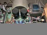
The power cap cannot see the value as there is only a reference sign, but they are big with over 2" diameter and 5" high, I think the capacity might be over 500mf.😉
The power cap cannot see the value as there is only a reference sign, but they are big with over 2" diameter and 5" high, I think the capacity might be over 500mf.😉
Yes......your'e still alive & kicking...ok at 550V B+ ..only true tetrode op for that amp, hum modulation possibilities can also be attributed to a scruffy screen grid supply.
If the amp was UL operated, only pristine KT88's could be used at that B+.
As you mention EL34's, screen grid B+for tetrode is quite a bit lower and should be well regulated. Since the tubes in the amp may not in virgin state, if a fault exists it would seem a pity to put new-on's in....esp if screen grid B+ is higher than it should be. ..Play safe...you mentioned the other amp is working....what is screen grid volts compared to the poor one ?
B+ has a 1A launch capability and plenty of joules..........I've wooden seat to put my butt on for such amps.
What are the driver tubes.....?? 6SN7 in cathode follower ?
rich

Hi,
Sounds as if there's a groundloop somewhere....
Cheers, 😉
I isolated the driver stage and no hum at all!...only when I reconnect it there is hum.
Sounds as if there's a groundloop somewhere....
Cheers, 😉
Check the P+ supply's ripple first.
Assuming a common ground between the two channel's of power supply, you can *remove* the B+ lead from the "good" channel and apply it's power via a clip lead to the B+ point on the output board and determine quickly if it is the PS or something else. (of course, remove the original PS B+ connection and make sure it doesn't hit ground or zap you!)
Make sure your bias is good on all the tubes.
Make sure your tubes are all good.
Make sure you have cathode connections (non broken cathode resistors) on each tube.
Check each tube's plate current, screen current and cathode current (same as plate current, but easier to check)
A big imbalance in the output stage will make for hum in the output.
_-_-bear
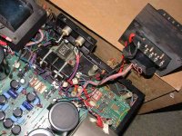
I discovered a plate at the back said its 150W output power. I attach one more picture showing the PS board. The driver tubes are 12AT7A, input in parallel as voltage amplifier and the second tube plate load driving the output tubes, sort of williamson type I suppose...
Attachments
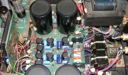
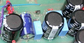
That blue electrolytic ton the left of the eline transis......what is it's voltage/cap value ?
That eline tranny could be part of the neg bias (simple pass smoothing)....The pnp often were silvered on one side but..I'm only suspecting.
richj
That eline tranny could be part of the neg bias (simple pass smoothing)....The pnp often were silvered on one side but..I'm only suspecting.
richj
The Q1 transistor is in the driver supply circuit, left side is the AC supply to a bridge rectifier then passing the the Q1 and a network of voltage division and out to the right side thru the big caps. The Q1 has on one side a silver plate...but no reference in it to check with...The blue ecap is 10mf450V.
The negative power tubes bias supply is in a separate circuit.
The negative power tubes bias supply is in a separate circuit.
- Status
- Not open for further replies.
- Home
- Amplifiers
- Tubes / Valves
- Tube monster amplifier