
So far I have no intention, I somehow prefer the AD811 and I think it performs better as an I/V than the OPA861.Try opa861 for i/v then if you need put a buffer tube....
It is true that neither of them is easy to implement as I/V, especially AD811 which is a video op.amp. and needs a small heatsink at higher voltages.
Attachments
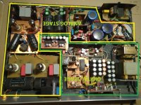
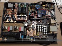
Last weekend I finally removed the last IC regulator (ADM7151) from the power supply of the PMD100 filter. (pin 22 (VDD2)-interface )
Now all regulators are modified discrete shunt type for PCM1702 and PMD100. Unfortunately, I do not have measuring equipment at home with which to compare discrete regulators and IC reg. In the DAC itself, if I look with an oscilloscope, small differences are noticeable on pin 22, where noise of ~5MHz or ~12MHz is present, depending on whether the DAC is in 'mute' or not.
However, the difference in sound is noticeable regardless of the fact that this regulator is only for PMD100 interfaces.
It's hard for me to describe the change, especially in English, but the sound is more natural, more dynamic, vocals and piano sound wonderful👍
The next goal is to make the same regulator but for +/-10V for the test I/V stage with the AD811.
Attachments

That 6HM5 is pretty terrible, variable mu, why not a D3a (or similar) in triode mode?I can see that the DIY DACs has come to life, but I don't see any progress around the output-analog stage. Always the same story with passive conversion or op.amps. In contrast, here is a slightly different solution, the input lamp receives the signal at the cathode and amplifies it and sends it further to the white cathode follower which gives an output with very low resistance .Russian 6S4P with cathode resistor correction can be used instead of 6HM5. Circuit has been tested for now with the current dac PCM1702 which outputs +/- 1.2mA (similar to AD1862) , it will soon be tested with +/- 3.2mA, in fact three PCM1702 in parallel. The power supply for the tubes was performed with a serial low-noise regulator for 260V, the circuit was modified with better reference and taken from ARC LS25MKII. All other important regulators in the DAC itself are shunt type from Mr. Walt Jung with low-noise op.amps and low-noise references. Special attention in the DAC is paid to power supplies and regulators which is really heard in the final sound.
I am now working on a new DAC with a TDA1547 that will also have tubes in the output stage section.
Direct couple the cathode to the DAC output and servo its cathode to a negative voltage.
Avoid coupling caps and DC offset on the DAC R2R output.
The load on the constant current load should be connected to the upper FET's source, where the load current is not "measured".
Old thread , nice job 😎