
You need a CCS instead of the 180 ohm cathode resistor. Will likely need a negative supply as you only have 1.6V to play with at the moment, although you might be able to change operating conditions and use a BJT CCS.
I would be glad if someone could show me a schematic of this 6922 in differential with CCS and negative voltage. Thanks
Here is a circuit I need some explanations
1- Why it works when VK is 4 volts or more above ground level ?
2- What kind of CSS doesn't need negative voltage ?
Thanks

1- Why it works when VK is 4 volts or more above ground level ?
2- What kind of CSS doesn't need negative voltage ?
Thanks
The ideal CCS is a two terminal device, so all that matters is the DC voltage drop across it.
The 4V in the circuit is the nominal Vgk at the tube's bias point, so the circuit is self-adjusting.
A negative supply voltage is not required for using a CCS. However, all practical CCS do require
a certain minimum DC voltage drop in order to function. The maximum DC voltage drop that
can be tolerated also depends on the CCS. There are many different CCS circuits and packaged devices.
For example, the LM334 can regulate 1uA to 10mA (set with a resistor), and will function with
a DC voltage drop (the compliance voltage) from 1V to 40V. Of course, the power dissipation
is also a limiting factor. Discrete circuits can handle much more current and/or voltage drop.
https://www.ti.com/lit/ds/symlink/l...Dhttps%3A%2F%2Fwww.ti.com%2Flit%2Fgpn%2Flm134
Last edited:
No idea if it matters for the thread starter's application, but PTAT current sources like the LM334 are very noisy.
If you can allow an extra AC coupling at the input, you can also put a resistor of a couple of kohm between the cathode resistor and ground, connect the 1 Mohm grid leak to the point where these resistors are joined and add that extra capacitor at the input.
If you can allow an extra AC coupling at the input, you can also put a resistor of a couple of kohm between the cathode resistor and ground, connect the 1 Mohm grid leak to the point where these resistors are joined and add that extra capacitor at the input.
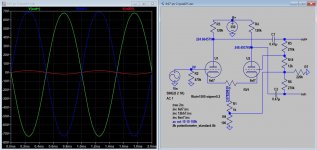
In a LTP or differential amp the bigger the tail resistor the better as it looks more like a CCS. Usually you allow about 25% to 1/3 HT across the tail, in your case 40v, 120v isn't much and your running the valve at quite high Ik. Anyhoo, I've knocked up a very quick schematic to show the sort of thing you want. It's very rough, I drew no loadline so it's just for illustration purposes.
Andy.
Andy.
Attachments
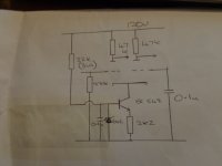
Here is the original schematic in the phono stage. There's a parallel fet single ended stage in front of this circuit and a passive equalization after it. I suspect that this circuit doesn't operate the 6922 at it's best so I thought upgrading it by raising the V+ to 120V and using more current on both tubes. The square waves at +- 30 hz with this circuit doesn't have straight lines but are a little wavy (not tilted). It is strange they take single ended signal to do balanced signal.

How can we determine the nominal Vgk of a tube so the circuit will be self adjusting ? (plates curves ?)The ideal CCS is a two terminal device, so all that matters is the DC voltage drop across it.
The 4V in the circuit is the nominal Vgk at the tube's bias point, so the circuit is self-adjusting.
On the tube's Iplate vs Vplate curves, plot the value of the CCS/2, which is a horizontal line at Icss/2,
and then determine where that line intersects the load line for your circuit. The load line is a line between
the two points: (Vplate = B+, Iplate = 0) and (Vplate = 0, Iplate = B+/Rplateresistor).
Where those two lines intersect, read off the Vgrid voltage that will result. That Vgk voltage will appear in
the circuit automatically if both of the tube sections conform to their typical characteristic curves.
Variations in the characteristics between the two tube sections of the tube differential amplifier will result in the
two sections not sharing the total CCS current equally. In this case the two DC plate voltages in the circuit will differ,
since the two Vgk will be forced to be equal, because both of the grids are at 0VDC, and the cathodes are connected.
Last edited:
J511 5.6mA makes more sense.Here is the original schematic in the phono stage. There's a parallel fet single ended stage in front of this circuit and a passive equalization after it. I suspect that this circuit doesn't operate the 6922 at it's best so I thought upgrading it by raising the V+ to 120V and using more current on both tubes. The square waves at +- 30 hz with this circuit doesn't have straight lines but are a little wavy (not tilted). It is strange they take single ended signal to do balanced signal.View attachment 1014886
- Home
- Amplifiers
- Tubes / Valves
- Tube differential gain