Hi all,
I wanna ask you about tube voltage swing and their relation....
Let use example EL84, if biased at -9V. Does it mean the tube will need twice the voltage for plate to perform a full swing (from 0 V to -18 V) ?
because if it's true what about the "free lunch" or "monkey" technique which use voltage from cathode ? does that mean the voltage given to the driver is just enough to drive the output tube...
if I design SE EL84 with bias at -9V, assumed input signal 1V, do I have look for driver that has gain around 9X?
I tried to read RDH but since my english is poor, i cannot clearly understand it...
thank for your help and regards...
A good way to make sense of all this might be to downolad some plate curves for the EL84 ( try here ). You will notice the relationship between grid and plate voltages - for a small change in grid voltage you get a much larger change in plate voltage. This ratio (amplification factor) varies for different types of tube but is generally lower for power tubes and higher for signal tubes.
The amount by which the grid voltage needs to change in each direction (swing) is decided by how much swing you require in plate voltage (depends on required power output and power supply voltage)
Bias voltage sets the dc conditions for the circuit which will stay largely unchanged throught the operating range of a single ended amp.
Applying a 1v ac signal to the grid (swinging between -1 and +1 v) will result in the grid swinging between -10 and -8 v. The maximum voltage you could apply to the grid at a -9v bias point would be +9v as anything higher would drive the grid positive (not allowed in most tubes)
Probably best to leave monkey and free lunch arrangements for another day but all of the above still applies to them, its just that they are designed to allow direct coupling of the driver to the grid of the power tube with out the use of a blocking capacitor.
Not very good at explaining all this stuff but I hope it helps as a starting point
Hi
There has been a thread some time ago where the tube gurus from this forum give guidance to a member who was also designing a amplifier using the EL84 at the output. If you can find the thread you will find lots of interesting information about the needed gain, use of NFB and so on.
Erik
There has been a thread some time ago where the tube gurus from this forum give guidance to a member who was also designing a amplifier using the EL84 at the output. If you can find the thread you will find lots of interesting information about the needed gain, use of NFB and so on.
Erik
I was referring to this thread. Hope it helps a bit!
http://www.diyaudio.com/forums/showthread.php?s=&threadid=63926&highlight=
Erik
http://www.diyaudio.com/forums/showthread.php?s=&threadid=63926&highlight=
Erik
Hi all, sorry for long reply...
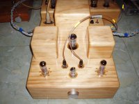
been busy with direct coupled amp.... It sound fast and Tight It helps bad quality OT specially low and high extention but become harsh on treble if we use good quality tranformer...
all i wanna is now playing with the loadline of EL84 (right now my EL84 plate voltage 330, cathode 109, and grid is around 100V with current around 36mA)
can someone who has experienced with EL84, the best loadline for el84... i have several OT that suit for this babies (3k5, 4K, 5K and 6k5)...
also wanna ask you about the load line. How do we plot the load line on Plate Characteristic. If I use 5K OT and use plate voltage 200V. would it be 40mA on plate (200K/5000 Ohm=0.040A)?
can some one tell me how to calculate or use load line?
Attachments
I will try to assist you...
The first important thing when monkeying with plate loads is to make sure you have the correct plate curves.. With pentodes it is imperative you choose the curves for the correct SCREEN VOLTAGE ......
Based on your info...You have 221 V from plate to cathode... and you have the tube biased to -9v ...this set up is drawing 36mA...
What voltage are you applying to the screen and how is it derived?? How well is it regulated?? Are you using Ultra-Linear arrangement??? Is this pentode wired???
Chris
Thank you for your assist cerrem
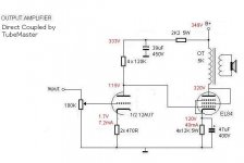
I wired screen and plate together (triode mode).
and for your info i use 12AU7 for driver using 30K as plate resistor and 235 Ohm at cathode. Plate voltage around 100V and plate current around 7,6~8mA.
I wired screen and plate together (triode mode).
and for your info i use 12AU7 for driver using 30K as plate resistor and 235 Ohm at cathode. Plate voltage around 100V and plate current around 7,6~8mA.
I looked at the EL84 TRIODE curves.... At 221V from plate to cathode..biased to 9 volts you get about 18mA ???? I don't see how you are getting 36mA..
Unless you are using two valves in parallel????
This is Single Ended application ?????
What EXACTLY are you trying to achieve??? This way i can better assist you......
Chris
Unless you are using two valves in parallel????
This is Single Ended application ?????
What EXACTLY are you trying to achieve??? This way i can better assist you......
Chris
Apologize me if my explanation is confusing you here is my experiment. It's 40 mA as i took a measurement again yesterday.
Yes, This is a single ended application in Triode Connected, it's designed by "Michael" the Tube Master. You know how dangerous when dealing direct coupled especially when driver tube fails. But Since this amp has very good sound. then my plan is trying to change the topology in order to make output tube still safe even when driver tube is still cold (during wrm up) or fail. From many direct coupled article i read, i see that monkey and DRD are safe way to do it... I just think if people can apply them on DHT, then can i apply to Non-DHT? I know there's many factor that i have to consider when performing the Monkey or DRD to Non-DHT tube... That what I want to know and achieve.....
best regards
Attachments
- Status
- Not open for further replies.
- Home
- Amplifiers
- Tubes / Valves
- Tube design question