I was wanting to build a tube DAC using Wolfson DAC's,I found an evaluation board at Mouser electronics,has anyone had any experience with these boards?
Take a look at the stuff Twisted Pear is doing with the Wolfson WM8740 DAC. (See the Opus thread)
http://www.twistedpearaudio.com/opus/opus.aspx
http://www.twistedpearaudio.com/opus/opus.aspx
Yes, opus module is cheaper and more "modular" than the evaluation board.
The major problem is to design an output stage using tubes as the output is differential voltage.
You can see this post : http://www.diyaudio.com/forums/showthread.php?s=&threadid=116282&highlight=
I did not yet try any solution
The major problem is to design an output stage using tubes as the output is differential voltage.
You can see this post : http://www.diyaudio.com/forums/showthread.php?s=&threadid=116282&highlight=
I did not yet try any solution
mgm31 said:Yes, opus module is cheaper and more "modular" than the evaluation board.
The major problem is to design an output stage using tubes as the output is differential voltage.
You can see this post : http://www.diyaudio.com/forums/showthread.php?s=&threadid=116282&highlight=
I did not yet try any solution
You can use a transformer to convert differential voltage out to unbalanced output. (This would be the same issue with the Wolfson eval board as well.) Most of the more recent high quality dacs have differential outputs.
kevinkr said:
You can use a transformer to convert differential voltage out to unbalanced output. (This would be the same issue with the Wolfson eval board as well.) Most of the more recent high quality dacs have differential outputs.
That's true, you can use Lundahl or Sowther :
-> It's a bit expensive
-> You don't need a tube stage !
One example with WM8740 : http://www.audiodesignguide.com/DAC_final/DacFinal.html
You could also use the TPA receiver board to drive a COD with a transformer based I/V and use a triode connected D3A or 5842 triode to gain that up. I am contemplating doing something similar with my dac which is based on a TPA receiver using the Wolfson WM8804 receiver and a pair of COD boards with PCM1798s installed.
Hypothetical:
I'm thinking something like a transformer 1:5 step up loaded with about 100 ohms on the secondary, reflecting just 4 ohms differential to the dac outputs - probably center tapped primary. Depending on dac chip and resistor values chosen you could have very close to a virtual earth (1 ohm with CT and resistor value cited) on the dac outputs and 50 - 100mVrms on the secondary - a gain of 20 - 40X (26 - 32dB) in the following stage using a high transconductance, low noise triode as previously mentioned to make the required gain. Both the mentioned types have low enough RP that they will drive 10K loads quite happily without a CF. Output levels can be tweaked for standard output levels simply by adjusting the value of the load resistor on the secondary of the I/V transformer.
Look at link below. I use his output stage with 2c51 or 6n6 tubes. They are for I/v or voltage Dac's also for symmetrical and asymmetrtical outputs.
http://www.lampizator.eu/
http://www.hififever.com/forum/viewtopic.php?t=1738
The SRPP tubestage is optimized for a output impedance of 8K,if a other output Z is require use link to calculate.
ftp://www.ict-net.net/tube.xls
http://www.lampizator.eu/
http://www.hififever.com/forum/viewtopic.php?t=1738
The SRPP tubestage is optimized for a output impedance of 8K,if a other output Z is require use link to calculate.
ftp://www.ict-net.net/tube.xls
Trying to understand circuit
Hi Koifarm
Thanks for the links, including pictures of your mods.
I am trying to understand the srpp circuit you posted. Lukasz Fikus on his Lampizator website calls his circuit 'an anode follower with dynamic active load'. Presumably, it is same as SRPP?
On the excellent excel file you kindly posted, what is the difference between SRPP a1 and SRPP k2, which appear to have different output impedances? Obviously, on your circuit you are not using the grid resistor between pins 2 & 6 of the 6h6p, and other grid resistor (Rg) is also 47ohms rather than 10000 ohms as in the excel file.
Sorry for the newbie questions.
Best regards
Fib
Koifarm said:Look at link below. I use his output stage with 2c51 or 6n6 tubes. They are for I/v or voltage Dac's also for symmetrical and asymmetrtical outputs.
http://www.lampizator.eu/
http://www.hififever.com/forum/viewtopic.php?t=1738
The SRPP tubestage is optimized for a output impedance of 8K,if a other output Z is require use link to calculate.
ftp://www.ict-net.net/tube.xls
Hi Koifarm
Thanks for the links, including pictures of your mods.
I am trying to understand the srpp circuit you posted. Lukasz Fikus on his Lampizator website calls his circuit 'an anode follower with dynamic active load'. Presumably, it is same as SRPP?
On the excellent excel file you kindly posted, what is the difference between SRPP a1 and SRPP k2, which appear to have different output impedances? Obviously, on your circuit you are not using the grid resistor between pins 2 & 6 of the 6h6p, and other grid resistor (Rg) is also 47ohms rather than 10000 ohms as in the excel file.
Sorry for the newbie questions.
Best regards
Fib
I have done just this and I can say the result is beyond my expectations:kevinkr said:Hypothetical:
I'm thinking something like a transformer 1:5 step up loaded with about 100 ohms on the secondary, reflecting just 4 ohms differential to the dac outputs - probably center tapped primary. Depending on dac chip and resistor values chosen you could have very close to a virtual earth (1 ohm with CT and resistor value cited) on the dac outputs and 50 - 100mVrms on the secondary - a gain of 20 - 40X (26 - 32dB) in the following stage using a high transconductance, low noise triode as previously mentioned to make the required gain. Both the mentioned types have low enough RP that they will drive 10K loads quite happily without a CF. Output levels can be tweaked for standard output levels simply by adjusting the value of the load resistor on the secondary of the I/V transformer.
http://www.diyaudio.com/forums/showthread.php?s=&threadid=100297
Re: Trying to understand circuit
Lukasz uses the same circuit with the 6n6p tube.
The output you can take from anode V1 (a1) or from kathode V2 (k2) that is the difference.
Only rk1 and rk2 are to calculate for the right output impedance. Rg is not needed.
The 47 ohm resistor is for the current to voltage transformation. ( also called I/V resistor). If the DAC has a current out then( example max 8mA) then the voltage over the I/V resistor 0.008A x 47 ohm = 0.376V then the tube stage amplifies it 11 times(6n6p) so the output will be 4 Vtt. So you calculate the output voltage. A smaller resistor gives a lower output.
If your DAC has a voltage output you can leave the I/V resistor and ad a 0,33uF capacitor in the audio input path.
With the SRPP it is important that you now the input impedance of the amplifier you connect to. This must be the same you calculate the SRPP for. If not there will be more distorsion as wanted. I build all types of tube output stages for DAC's and CD players but i like the SRPP stage the most with 6n6p( warmer sound) or ECC99 (allrounder).
If your amp has a higher input impedance you can simple lower the impedance by parallel a resistor to match the SRPP stage.
The SRPP circuit has several namens. Tubecad has a hole topic on it.FibCouple said:
Hi Koifarm
Thanks for the links, including pictures of your mods.
I am trying to understand the srpp circuit you posted. Lukasz Fikus on his Lampizator website calls his circuit 'an anode follower with dynamic active load'. Presumably, it is same as SRPP?
On the excellent excel file you kindly posted, what is the difference between SRPP a1 and SRPP k2, which appear to have different output impedances? Obviously, on your circuit you are not using the grid resistor between pins 2 & 6 of the 6h6p, and other grid resistor (Rg) is also 47ohms rather than 10000 ohms as in the excel file.
Sorry for the newbie questions.
Best regards
Fib
Lukasz uses the same circuit with the 6n6p tube.
The output you can take from anode V1 (a1) or from kathode V2 (k2) that is the difference.
Only rk1 and rk2 are to calculate for the right output impedance. Rg is not needed.
The 47 ohm resistor is for the current to voltage transformation. ( also called I/V resistor). If the DAC has a current out then( example max 8mA) then the voltage over the I/V resistor 0.008A x 47 ohm = 0.376V then the tube stage amplifies it 11 times(6n6p) so the output will be 4 Vtt. So you calculate the output voltage. A smaller resistor gives a lower output.
If your DAC has a voltage output you can leave the I/V resistor and ad a 0,33uF capacitor in the audio input path.
With the SRPP it is important that you now the input impedance of the amplifier you connect to. This must be the same you calculate the SRPP for. If not there will be more distorsion as wanted. I build all types of tube output stages for DAC's and CD players but i like the SRPP stage the most with 6n6p( warmer sound) or ECC99 (allrounder).
If your amp has a higher input impedance you can simple lower the impedance by parallel a resistor to match the SRPP stage.
Re: Re: Trying to understand circuit
Hi Koifarm
Thans for your detailed reply.
Thanks. That solves the puzzle for me. Obviously, I still need to read a lot about theory. 😉
I have built output stage based on Lukasz circuit, based on 6n1p. Now I know how to calculate the out impedance properly, as I am taking output from k2.
The music becomes so much real & involving, after doing this mod, replacing the discrete stage previously. The digital sound is getting closer & closer to my EMT930, which I couldnt have imagined few months ago. 🙂
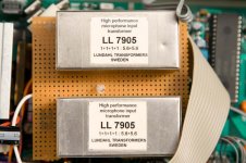
Recently, I installed Lundahl 7905 interstage transformers. Now my resistor is 22 ohms, giving 25 mV with 1 KHz tone, hopefully? staying within Phillips recommended 25mV for TDA1541A S1 to prevent distortion. The jump in quality was again very big. The bass is deeper & tighter, mids even more analog like. Even my 10 yr old preferred it each time in a double blind test & commented on the bass & 'live' like quality.
Unfortunately, I have been unable to find the input impedance of my tube technology HB70 amplifier from manufacturer & dont know any other to find out. Now my calculated dac output stage impedance is 2.2 K. What will be recommended amp input impedance? I presently have 250K resistor in parellel after tube stage.
Best regards
Fib
Hi Koifarm
Thans for your detailed reply.
Koifarm said:
The output you can take from anode V1 (a1) or from kathode V2 (k2) that is the difference.
Thanks. That solves the puzzle for me. Obviously, I still need to read a lot about theory. 😉
I have built output stage based on Lukasz circuit, based on 6n1p. Now I know how to calculate the out impedance properly, as I am taking output from k2.
The music becomes so much real & involving, after doing this mod, replacing the discrete stage previously. The digital sound is getting closer & closer to my EMT930, which I couldnt have imagined few months ago. 🙂
Recently, I installed Lundahl 7905 interstage transformers. Now my resistor is 22 ohms, giving 25 mV with 1 KHz tone, hopefully? staying within Phillips recommended 25mV for TDA1541A S1 to prevent distortion. The jump in quality was again very big. The bass is deeper & tighter, mids even more analog like. Even my 10 yr old preferred it each time in a double blind test & commented on the bass & 'live' like quality.
Koifarm said:
With the SRPP it is important that you now the input impedance of the amplifier you connect to. This must be the same you calculate the SRPP for. If not there will be more distorsion as wanted.
If your amp has a higher input impedance you can simple lower the impedance by parallel a resistor to match the SRPP stage.
Unfortunately, I have been unable to find the input impedance of my tube technology HB70 amplifier from manufacturer & dont know any other to find out. Now my calculated dac output stage impedance is 2.2 K. What will be recommended amp input impedance? I presently have 250K resistor in parellel after tube stage.
Best regards
Fib
Attachments
- Status
- Not open for further replies.
- Home
- Source & Line
- Digital Source
- Tube DAC