Hi, I have this DAC that comes out a little low compared to my other sources. Maybe I could change tubes with others with a higher MU..Clearly tweaking the polarization?
It features 2 pentodes connected to a triode with this acronym printed on it "6Ж52П".
Regarding the translation from Cyrillic, I honestly don't understand if they are 6J52P or 6Z52P, I would like your opinion on the matter.
I would also like to know the MU when connected to triode. Two links online lead me to this:
https://www.bartola.co.uk/valves/2013/11/17/6ж52п-6z52p-in-triode-mode/ (MU 76.5)
....and to this:
https://www.bartola.co.uk/valves/2015/07/04/lcr-phono-design-notes-part-ii/#more-4746 (MU 54.81).
In your opinion is it the measurement of the same valve? Because it mentions 6J52P in one link and 6Z52P in the other... and I don't understand why there is so much difference in MU. Maybe measurements taken under different conditions make that much difference?
Oh well..I would simply like to know the MU also to adjust myself with other possible alternatives, with higher Mu, such as perhaps a possible E810F, D3A..or 6z51p which has an MU of 80, visible at this link:
https://www.bartola.co.uk/valves/2013/02/23/russian-pentodes-in-triode-mode/#more-1264
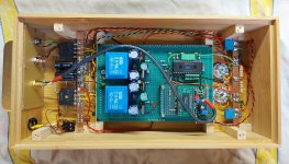
Apart from the MU issue, partly to know how this DAC was implemented, partly to learn something, I still made some measurements around the tube.
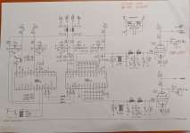
Compared to the diagram the seller provided me, I notice several differences.
The DAC output pins go straight to the tube and, unlike the diagram provided, no transformer, no filter. There is only one r of 56/57ohm towards ground (I think it is for the I/V conversion)... and 1k as a grid stopper, if I'm not being stupid. Why is there no filter? Perhaps the miller capacity entering the tube is exploited to "generate" it?
For the rest there are no bypass caps on the cathode, so I can assume that I could gain output signal level by bypassing the rk with an electrolytic cap. But since, if I remember correctly, the signal passes through it, perhaps I would prefer to use some diode... LED... or another type.
Always hoping not to say nonsense. It's correct? with a diode, at the same voltage (1.1v) I should have maximum gain, right?
In fact I then noticed differences from the scheme. The B+ is not 180vdc as per the diagram but 151/154vdc.
The RA is 6.7k and, if I'm not doing the math wrong, the current flowing in the tube is (1.06v : 180ohm) ...5.88mA.
Given the way the tube bends are, whether it is a 6J52P or 6Z52P, it seems to me that it is working with little current and therefore also in a slightly unlucky area of the bends.
I'm highly inexperienced so I've been talking nonsense for a while. Furthermore, reading a lot online about this tube or similar... they seem to like much higher currents than a paltry 5.88 mA.
Was it a design choice to have a certain sound timbre?
Well, that's all. I haven't listened to the object much yet but I think it sounds very pleasant, very good, but it could be that we could do better, certainly.
First of all I would tend to try to increase the output level.
I'd love to get some help, some advice, some opinions regarding the current polarization and the other "points" I highlighted in the post if you have time!
Anyway, thanks for any words.
It features 2 pentodes connected to a triode with this acronym printed on it "6Ж52П".
Regarding the translation from Cyrillic, I honestly don't understand if they are 6J52P or 6Z52P, I would like your opinion on the matter.
I would also like to know the MU when connected to triode. Two links online lead me to this:
https://www.bartola.co.uk/valves/2013/11/17/6ж52п-6z52p-in-triode-mode/ (MU 76.5)
....and to this:
https://www.bartola.co.uk/valves/2015/07/04/lcr-phono-design-notes-part-ii/#more-4746 (MU 54.81).
In your opinion is it the measurement of the same valve? Because it mentions 6J52P in one link and 6Z52P in the other... and I don't understand why there is so much difference in MU. Maybe measurements taken under different conditions make that much difference?
Oh well..I would simply like to know the MU also to adjust myself with other possible alternatives, with higher Mu, such as perhaps a possible E810F, D3A..or 6z51p which has an MU of 80, visible at this link:
https://www.bartola.co.uk/valves/2013/02/23/russian-pentodes-in-triode-mode/#more-1264
Apart from the MU issue, partly to know how this DAC was implemented, partly to learn something, I still made some measurements around the tube.
Compared to the diagram the seller provided me, I notice several differences.
The DAC output pins go straight to the tube and, unlike the diagram provided, no transformer, no filter. There is only one r of 56/57ohm towards ground (I think it is for the I/V conversion)... and 1k as a grid stopper, if I'm not being stupid. Why is there no filter? Perhaps the miller capacity entering the tube is exploited to "generate" it?
For the rest there are no bypass caps on the cathode, so I can assume that I could gain output signal level by bypassing the rk with an electrolytic cap. But since, if I remember correctly, the signal passes through it, perhaps I would prefer to use some diode... LED... or another type.
Always hoping not to say nonsense. It's correct? with a diode, at the same voltage (1.1v) I should have maximum gain, right?
In fact I then noticed differences from the scheme. The B+ is not 180vdc as per the diagram but 151/154vdc.
The RA is 6.7k and, if I'm not doing the math wrong, the current flowing in the tube is (1.06v : 180ohm) ...5.88mA.
Given the way the tube bends are, whether it is a 6J52P or 6Z52P, it seems to me that it is working with little current and therefore also in a slightly unlucky area of the bends.
I'm highly inexperienced so I've been talking nonsense for a while. Furthermore, reading a lot online about this tube or similar... they seem to like much higher currents than a paltry 5.88 mA.
Was it a design choice to have a certain sound timbre?
Well, that's all. I haven't listened to the object much yet but I think it sounds very pleasant, very good, but it could be that we could do better, certainly.
First of all I would tend to try to increase the output level.
I'd love to get some help, some advice, some opinions regarding the current polarization and the other "points" I highlighted in the post if you have time!
Anyway, thanks for any words.
Attachments


6Ж52П is often referred as 6J52P, 6Z52P, 6Zh52P, using the latin alphabet . They are all the same tube.6Ж52П".
Regarding the translation from Cyrillic, I honestly don't understand if they are 6J52P or 6Z52P, I would like your opinion on the matter.

Hello,
What you wrote in your initial post are good points. I think you can increase the gain by replacing the Rk with a LED. The I/V resistor can not go beyond a certain value, because distortion goes up, too. 10 ohms is safe, but some say it can go up to as much as 100 ohms. I never tried it. 56 ohms looks good as a start.
What you wrote in your initial post are good points. I think you can increase the gain by replacing the Rk with a LED. The I/V resistor can not go beyond a certain value, because distortion goes up, too. 10 ohms is safe, but some say it can go up to as much as 100 ohms. I never tried it. 56 ohms looks good as a start.
Hi 🙂 at this interesting link you can clearly see that 30/35 ohm would be the maximum value... beyond that things get worse.
https://www.mvaudiolabs.com/digital/tda1541-iv-resistor-selection/
I think I read that the datasheet recommends 12.5ohm. So why do many people use much higher values... precisely, as you say, up to 100ohm?
The most common values are 50/82ohm.
The higher the value of the I/V resistance, the more output millivolts are obtained? Is this perhaps the reason why we are "high" with the values of this R? Maybe with a 12.5ohm R (as the datasheet says)... would the output signal be very low?
Thanks again.
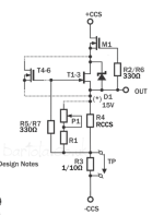
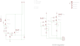
This is a possible solution using Bartolas ccs https://www.bartola.co.uk/valves/for-sale/ccs-pcb/
With 150V B+ and 15mA you can not use an anode resistor.
Why not try an 1:2 transformer to get higher output and hf filtering?

With 150V B+ and 15mA you can not use an anode resistor.
Why not try an 1:2 transformer to get higher output and hf filtering?
As told many times, I must have a little test setup. With a good sound card and Arta or REW softwareHi 🙂 at this interesting link you can clearly see that 30/35 ohm would be the maximum value... beyond that things get worse.
https://www.mvaudiolabs.com/digital/tda1541-iv-resistor-selection/
I think I read that the datasheet recommends 12.5ohm. So why do many people use much higher values... precisely, as you say, up to 100ohm?
The most common values are 50/82ohm.
The higher the value of the I/V resistance, the more output millivolts are obtained? Is this perhaps the reason why we are "high" with the values of this R? Maybe with a 12.5ohm R (as the datasheet says)... would the output signal be very low?
Thanks again.
Then you check the frequency response modifing the the resistors network and, in case to put a Zobel network on secondary.
It is simply, just some time to spent.
And leave the sand out from tube.
🤣
Walter
I would think a grounded grid tube I/V stage would fair better than a transformer.This is a possible solution using Bartolas ccs https://www.bartola.co.uk/valves/for-sale/ccs-pcb/
With 150V B+ and 15mA you can not use an anode resistor.
Why not try an 1:2 transformer to get higher output and hf filtering?
The transformer is just an addon, for filtering HF harmonics, the circuit can be used w/o it with half the output.I would think a grounded grid tube I/V stage would fair better than a transformer.
Anyway grounded grid is interesting and quite ingenious, do you have an example with HF filtering?
Brilliant thing about them is the tube filters it at the same time. So you can make a capacitor-less design.Anyway grounded grid is interesting and quite ingenious, do you have an example with HF filtering?
But if you are using medium voltage tubes like this one Tom Brooskie designed, you put it after the active i/v then it doesn't effect 1st order transients

this is the Digital stage done by me and my friend Andrea and published on Audioreview

We use the ESS9018 and the trafo are 3575 OCC from Sowter, to match correctly in termos of frequency response the selection of resistors on Dac out and on secondary to the tube circuit are very important.
The interface was Arduino, it read DSD until 512
The project was 2014!
Great sound but too heavy job
Walter
Well, here's the thing.
I measured the DAC, crap!
Absolutely non-linear frequency response (obvious given the unfortunate operating point).
Driven by the digital output of a Marantz CD50, track of a CD 1Khz 0db:
Output 1,47 Vrms on RCA connector (no bypass RK) - THD 0,22% - GAIN 18,6 Times
Output 3,54 Vrms on RCA connector (1000uF bypass RK) - THD 1,27% (stupid test!) - GAIN 44,8 Times
Output 79 mVrms on I/V R (56ohm)...with valve stage connected
Driven by the digital output of a Marantz CD50, track of a CD 1Khz -10db (no bypass RK) :
20hz = 0,435 mVrms
30hz = 0,453 mVrms
100hz = 0,473 mVrms
1khz = 0,494 mVrms
5khz = 0,791 mVrms
10khz = 1,088 mVrms
15khz = 1,239 mVrms
20khz = 1,306 mVrms
....better not to comment, a tragedy!
It is clear that I do not have enough voltage for this tube, as well as little current, current 5.88mA. I know that for this tube you need a lot more current and also quite a bit more voltage.
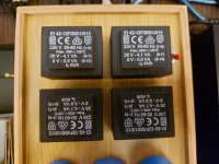
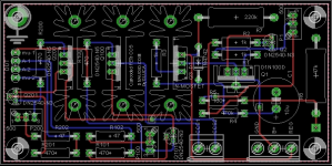
I don't intend to undo everything and change the 4 transformers you see in the attached photo, they produce the voltage for the filaments and the anode.
Currently the 4 secondaries at 8v are all in parallel and power the filaments. The 4 secondaries at 26v are all in series for B+.
Unfortunately I can't connect them in any other way to get a higher B+. Yes, actually I could do that, but I would lose some current to the filaments. So nothing to do.
Solution? Tube change!
I have a pair of e88cc siemens gold pins perfectly matched and a pair of ecc88 philips, also new and paired.
Among the tubes I have I think these are the most suitable, in my opinion with these tubes I can get 2Vrms output and I have enough current and voltage to make them work well.
I have a couple of questions:
- Can I bias these tubes without worrying about the input impedance of the tube stage seen by the TDA?
I think so. Lampizator-Poland has modified dozens of CD players by placing only the R I/V before the tubes, but I would like confirmation.
- Using a pair of these tubes I would have (ecc88 / e88cc), in my beginner's head, to summarize, 4 options:
1) SRPP
2) Common Cathode + Follower
3) Triodes in parallel
4) Mu Follower
I tested the power supply by loading the B+ with resistors. I have these currents and voltages at my disposal.
LOAD B+
12mA 150V
23mA 139V
39mA 121V
The less current I consume from the B+... the better, as the voltage for the filaments is also affected. This should be taken into account.
I would always tend towards solutions with "less" current (and perhaps also "less voltage") as I would like to keep some margin in case more filtering is needed.
What would you do with these voltages and currents and... tubes available?
I don't pretend it's the best DAC in the world, I already have 3 DACs and I live happily.
I would just like to put it in a position to sound better than with the 6Ж52П under current and undervoltage!
Thanks a lot ! 🙂
I measured the DAC, crap!
Absolutely non-linear frequency response (obvious given the unfortunate operating point).
Driven by the digital output of a Marantz CD50, track of a CD 1Khz 0db:
Output 1,47 Vrms on RCA connector (no bypass RK) - THD 0,22% - GAIN 18,6 Times
Output 3,54 Vrms on RCA connector (1000uF bypass RK) - THD 1,27% (stupid test!) - GAIN 44,8 Times
Output 79 mVrms on I/V R (56ohm)...with valve stage connected
Driven by the digital output of a Marantz CD50, track of a CD 1Khz -10db (no bypass RK) :
20hz = 0,435 mVrms
30hz = 0,453 mVrms
100hz = 0,473 mVrms
1khz = 0,494 mVrms
5khz = 0,791 mVrms
10khz = 1,088 mVrms
15khz = 1,239 mVrms
20khz = 1,306 mVrms
....better not to comment, a tragedy!
It is clear that I do not have enough voltage for this tube, as well as little current, current 5.88mA. I know that for this tube you need a lot more current and also quite a bit more voltage.
I don't intend to undo everything and change the 4 transformers you see in the attached photo, they produce the voltage for the filaments and the anode.
Currently the 4 secondaries at 8v are all in parallel and power the filaments. The 4 secondaries at 26v are all in series for B+.
Unfortunately I can't connect them in any other way to get a higher B+. Yes, actually I could do that, but I would lose some current to the filaments. So nothing to do.
Solution? Tube change!
I have a pair of e88cc siemens gold pins perfectly matched and a pair of ecc88 philips, also new and paired.
Among the tubes I have I think these are the most suitable, in my opinion with these tubes I can get 2Vrms output and I have enough current and voltage to make them work well.
I have a couple of questions:
- Can I bias these tubes without worrying about the input impedance of the tube stage seen by the TDA?
I think so. Lampizator-Poland has modified dozens of CD players by placing only the R I/V before the tubes, but I would like confirmation.
- Using a pair of these tubes I would have (ecc88 / e88cc), in my beginner's head, to summarize, 4 options:
1) SRPP
2) Common Cathode + Follower
3) Triodes in parallel
4) Mu Follower
I tested the power supply by loading the B+ with resistors. I have these currents and voltages at my disposal.
LOAD B+
12mA 150V
23mA 139V
39mA 121V
The less current I consume from the B+... the better, as the voltage for the filaments is also affected. This should be taken into account.
I would always tend towards solutions with "less" current (and perhaps also "less voltage") as I would like to keep some margin in case more filtering is needed.
What would you do with these voltages and currents and... tubes available?
I don't pretend it's the best DAC in the world, I already have 3 DACs and I live happily.
I would just like to put it in a position to sound better than with the 6Ж52П under current and undervoltage!
Thanks a lot ! 🙂
Attachments
...thinking about it..considering the voltages and currents available..perhaps a better option 2 or 3...
Maybe I would prefer option 3.
I'd like to try option 3, I've never built anything with triodes in parallel. But I think I can have low output impedance, low noise...and the right gain. Could I get away with about 24mA (6mA per triode)?
Maybe I would prefer option 3.
I'd like to try option 3, I've never built anything with triodes in parallel. But I think I can have low output impedance, low noise...and the right gain. Could I get away with about 24mA (6mA per triode)?
Don´t complicate things for yourself. Use only one half of the ECC88 for each channel! The wimpy power supply seems to work acceptable with ca 5mA, which is good enough for the single 88´s. Don´t load it more, as 150V is still on the low side. Once again, if you want it to work properly(horizonal loadline) and want low Zout, go for a Bartola CCS/mufollower from Bartola: https://www.bartola.co.uk/valves/for-sale/ccs-pcb/
I once bought the same style unpopulated PCB´s from an Italian maker(Gianluca) here on diyaudio, can supply you with a pair if you need. https://www.diyaudio.com/community/threads/pcb-for-cascoded-ixys-ccs-tube.190379/


I once bought the same style unpopulated PCB´s from an Italian maker(Gianluca) here on diyaudio, can supply you with a pair if you need. https://www.diyaudio.com/community/threads/pcb-for-cascoded-ixys-ccs-tube.190379/
Attachments
Last edited:


- Home
- Amplifiers
- Tubes / Valves
- Tube DAC with TDA1541 and 6Ж52П pentode (6J52P or 6Z52P ??)