Hello everyone,
I decided to make a tube buffered IC amp, although tubers or gaincloners won't like it.
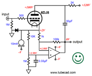
And I liked tubecad's tube buffered (with CCS) chipamp design. However, I have 12AU7, 5751 and a few 12AX7. To be honest, I didn't want to buy a 6DJ8 just for this project.
However, the CCS on the cathode of the tube is 10ma and this would be a high bias for the tubes I have. So I decided to use 2x parallel 12au7. This would give me a quiet bias of 5ma per cathode.
I decided to use LM317L, which I have used before and was happy with, set to 10ma, as the CCS.
And this is the circuit that came out..
What I want to ask is, this circuit gives THD values like 0.05% in the simulation.. Also, according to the FFT results, the weighted harmonic is 2. (A harmonic that I personally like) Do you think something like this is possible? Or is this circuit worth making?
Thanks in advance..
PS: 317's resistor should be 120 not 150...
I decided to make a tube buffered IC amp, although tubers or gaincloners won't like it.
And I liked tubecad's tube buffered (with CCS) chipamp design. However, I have 12AU7, 5751 and a few 12AX7. To be honest, I didn't want to buy a 6DJ8 just for this project.
However, the CCS on the cathode of the tube is 10ma and this would be a high bias for the tubes I have. So I decided to use 2x parallel 12au7. This would give me a quiet bias of 5ma per cathode.
I decided to use LM317L, which I have used before and was happy with, set to 10ma, as the CCS.
And this is the circuit that came out..
What I want to ask is, this circuit gives THD values like 0.05% in the simulation.. Also, according to the FFT results, the weighted harmonic is 2. (A harmonic that I personally like) Do you think something like this is possible? Or is this circuit worth making?
Thanks in advance..
PS: 317's resistor should be 120 not 150...
Attachments

... or at least clamp the input(s) to VCC/VEE with a pair of diodes.
Also note that the tubes will be loaded by the 1 kΩ input impedance of the inverting LM3886. That may not be desirable.
I recommend that you read: https://neurochrome.com/pages/taming-the-lm3886-chip-amplifier, in particular the sections on grounding and decoupling.
I like the overall idea. I get the occasional request for a circuits like that, but I'm in no hurry to get back into the tube amp market.
Tom
Thank you for your kind replies.. I'd like to just try it. "Clamping inputs" is a good idea, when you consider the tube works at 120v..
In fact I don't understand the function of 30u cap (33u in my circuit) between B+ and chipamps output.. Is it like bootstrap?
In fact I don't understand the function of 30u cap (33u in my circuit) between B+ and chipamps output.. Is it like bootstrap?
By the way, dear Tom, I read your valuable notes while making modulus86 many years ago. Thanks.... or at least clamp the input(s) to VCC/VEE with a pair of diodes.
Also note that the tubes will be loaded by the 1 kΩ input impedance of the inverting LM3886. That may not be desirable.
I recommend that you read: https://neurochrome.com/pages/taming-the-lm3886-chip-amplifier, in particular the sections on grounding and decoupling.
I like the overall idea. I get the occasional request for a circuits like that, but I'm in no hurry to get back into the tube amp market.
Tom
And this is the blog I quoted;
https://tubecad.com/2010/01/blog0179.htm
Concerning 1K loading of tube..
You may be right.. In the simulation; I saw a dc offset of around 2v at the input node (the cathode) and a few tens of millivolts swing for a 1v input signal.. (to compansate 100x of chipamp gain I guess) So for this level of input impedance might not be a problem for 10ma biased tube stage??? What do you think?
Last edited:
I suggest you pull out your copy of Morgan Jones, Valve Amplifiers. You'll find that the output impedance of a CCS loaded grounded cathode is approximately ra, which for an ECC82/12AU7 is about 7.7 kΩ. Putting the two sections in parallel reduces this to 3.85 kΩ. Loading that with 1 kΩ forms a 4.85:1 voltage divider, so you only get ~20% of the gain of the tube.
Not only that, ra varies from tube to tube and also by the chosen operating point, so you have hardly any control over the gain.
And maybe that's what you want. Maybe that gives the tone that you're after. But it doesn't seem like the most robust design.
Personally, I'd look at something like an anode follower or similar circuit that uses some local feedback to reduce the gain of the tube stage, thereby making the gain dependent on a resistor ratio (which can be established with great precision) rather than a tube parameter (which varies all over the place). But that's me...
Tom
I'm guessing the LM3886 is configured as an inverting amp to preserve absolute phase input to output. But that could also be accomplished by swapping the speaker terminals. So how about a simple grounded cathode stage with un-bypassed cathode resistor? Set the gain around 2 and configure the LM3886 as a non-inverting amp with a gain of 11 (so Rf = 10 kΩ, Rgnd = 1 kΩ). That gives you a bit lower output impedance of the grounded cathode as it now has some feedback and it'll be loaded by the high input impedance of the non-inverting LM3886. Then swap the speaker terminals to preserve the phase input-to-output.
Just a thought.
Tom
Just a thought.
Tom
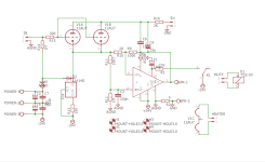
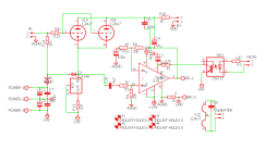
Dear Tom,
What do you think about that one?
Changed to non inverted configuration. And tubes loaded at ~21K??
And still, I don't know the function of the big cap connected between B+ to chipamps output... Do you think I should remove (looks like dangerous to me!)
What do you think about that one?
Changed to non inverted configuration. And tubes loaded at ~21K??
And still, I don't know the function of the big cap connected between B+ to chipamps output... Do you think I should remove (looks like dangerous to me!)
Attachments
Dear friend, I am a bit of a lazy DIYer. Also, I am not in the mood these days for personal reasons. To be honest, I am also quite upset that I still haven't finished this project.
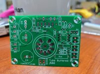
But I have serious hopes that I will finish it this week or the weekend and give it my first listen. Please excuse me.
I will inform you about the results soon.
Stay well.
But I have serious hopes that I will finish it this week or the weekend and give it my first listen. Please excuse me.
I will inform you about the results soon.
Stay well.
Nothing to be sorry for, motivation comes and goes, life throws curve balls, business as usual 🙂 ... I was just curious....
Good luck!
Good luck!
- Home
- Amplifiers
- Chip Amps
- Tube buffered LM3886