Hello, I'm trying to build a dac with a tube buffer output. I'm a "beginner" (I have built a KT88 srpp with my father) in electronics so I need some advise.
I'm following the instructions of Lukasz Fikus, he seems to have much experience with this kind of stuff.
http://www.lampizator.eu/UPGRADE/upgrade noval tubes to 6H6P.html
I want to build a srpp with 6H6P. (see down page of lampizator)
I have few questions.
1 what type of input cap shall I use ? electrolits ? mkp ?
2 Can I put the 6,3VAC of the transformer directly on the heaters without caps and not in DC ? (I think it is possible)
3 Where can I find a transformer with 6.3V and 115VAC secondaries ? (50VA) ? because I can't find anything. Note : I'm in France so primary voltage is 230VAC 50Hz.
4 About the "totem pole symetrical" schem that you can find on the link upper, can I use it directly like that with those values ? What kind of Ck shall I use ?
I'm sorry for my very bad english, I'm french you know ...
Thanks
I just finished Fikus' mod on a cheap plastic Marantz CD-40. It has soul and grabs your heart. Still not at vinyl soul but for CD it's marvelous. Best CDP I have owned and unquestionably the cheapest.
I used 6N1P's in SRPP per Lukasz' specs. FYI, I also bypassed all the surface mounted decoupling caps with .18uF MKT's and made the non-oversampling mods.
So you must be using a voltage output DAC, correct? The input cap is not required for current out DAC's like mine. If you need it the better the cap, the better the sound. This cap is directly in the signal path. I used Obbigato's for the output. I would have used the same for input given I needed it. Use your MKP's before you use 'lytics (least recommended).
You can use AC - try it. If you get hum, you might have to go DC.
I'm in the US so I don't have any make and model transformer recommendations but check the catalogs of all the makers you know of. Or, how 'bout this... Ask Lukasz if you can buy one from him (Poland uses the same voltage/cycle spec, right?)!
The cathode resistor defines the current the tube will pull. Lukasz says anything between 200 and 500ohm works with the 6N6P. There will be a value that suits your ear the best but for the most part those diffs are so subtle that it's very difficult to compare. Again, write Lukasz and ask if he has found that "ultimate optimum" cathode resistor value 🙂
Good luck on the project - if your results are anything like mine you will be amazed.
Thank you for your answers.
My dac is a voltage output yes but also a symetrical one !!! and that's why it has become more complicated for me. I cannot use lukaz's lampizators. He must be on holidays because He does not answer to my mails anymore ^^.
On a french forum, a guy told me tha tthe output voltage of the dac is 2V, wich is enough to go directly to my amp (a charlize I am building it too). So I need a buffer with a gain around 1 and not 10 like the srpp has with 6H6P. The idea is to make an "aikido" with, for example, ecc86 (anode voltage=24V ^^).
http://www.tubecad.com/2006/08/blog0075.htm
So no lampizator.
It is gonna be complicated for me, I'll see if I make it or not later
Then how about the cathode follower with 6N6P? I bought the 24bit/192KHz Cirrus Logic DAC from China and will try this next.
Here it is...
http://www.lampizator.eu/LAMPIZATOR/LAMPUCERA/MAX/IMG_5143.jpg
Here it is...
http://www.lampizator.eu/LAMPIZATOR/LAMPUCERA/MAX/IMG_5143.jpg
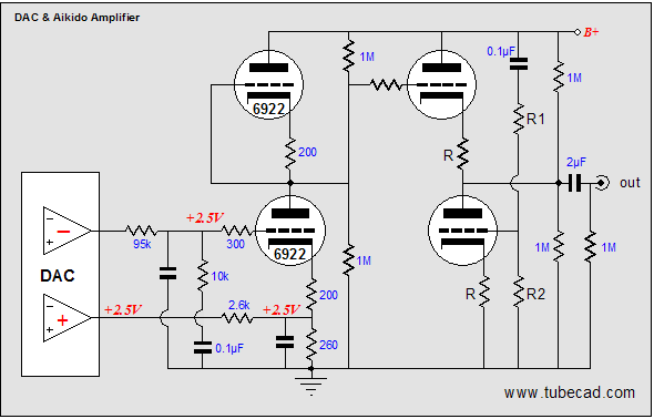
The aikido as the advantage of doing the exact same thing as the original aop. It suppress the pertubations create by the dac by using both + and - signals of the symetrical output of the cs4397. And it has laso a low pass filter. The cathode follower does not do that. So I think the aikido is way better than the cathode follower, but more complex.
Remember in the Aikido circuit shown there is a voltage divider, so your gain is reduced 90%. The voltage divider is important to maintain a high enough input impedance for the DAC.
You also have to bias the tube and select the resistor under the cathode to give 2.5V DC. In order to maintain a decent input impedance the tube selection becomes very small.
There is also the issue that Vout- will see a much higher input impedance.
So in reality the Aikido circuit ain't too hot for this application.
The Broskie cathode follower is probably much better.
Yes you are probably right (I'm not expert enough). But about the gain, I really don't need much gain, 1 is ok because I have a charlize amp after that so I don't need a too high output.
Maybe this kind of cathode follower is the best idea :
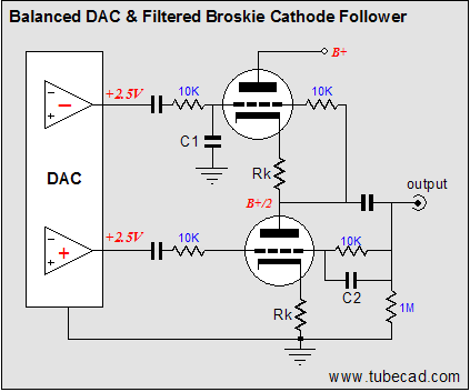
It is using both Vout+ and Vout- of the dac and it is filtered and as a gain of 1.
Wich Rk shall I choose for ecc86 ? I read 187 ohm but ... how can I calculate that ?
About the caps on the inputs ? what kind of caps shall I use ? at wich values ?
It is using both Vout+ and Vout- of the dac and it is filtered and as a gain of 1.
Wich Rk shall I choose for ecc86 ? I read 187 ohm but ... how can I calculate that ?
About the caps on the inputs ? what kind of caps shall I use ? at wich values ?
You need to choose an operating point and calculate the cathode resistor values
Then You need to calculate the input impedance of the tube stage .
.
You have a lot of studying to do.
Then You need to calculate the input impedance of the tube stage .
.
You have a lot of studying to do.
The easiest thing to do with a balanced output from a DAC is run it into a differential pair in Push Pull using an output transformer. You can even use a Hammond 124b which is nickel, cheap, and sounds very good.
Simple version has a single cathode resistor for the pair, better version has a constant current sink. Designs for a CCS are in Morgan Jones book Valve Amplifiers page 134, or on Allen Wright's site under his amplifier circuit.
Better still, put 5k in series on the + and - inputs (and before that something from each leg to earth, like 250k or whatever - depends on the DAC), and then put your shunt volume control across the two input grids. That way you have your volume control and the 5k resistors act in lieu of grid stoppers.
Choose whatever double triode you want for this, as long as the anode resistance is say under 10k. If you use the HAmmond 124b in stepdown it's 90k into 10k so this works. If you use other transformers 5k anode resistance may be better. Kevin has a lot of details of this kind of circuit on his website - see www.audioasylum.com K&K forum.
Andy
Hi Rafoo,
It' s an old thread but I was wondering what you came up with eventually. I'm looking for the same thing. Have you tried the broskie cathode follower.Thank you.
It' s an old thread but I was wondering what you came up with eventually. I'm looking for the same thing. Have you tried the broskie cathode follower.Thank you.
3 Where can I find a transformer with 6.3V and 115VAC secondaries ? (50VA) ? because I can't find anything. Note : I'm in France so primary voltage is 230VAC 50Hz.
Hi Rafoo,
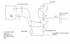
have a look to THIS Amplimo transformer. I used this one for my first circuit.
There is also a schematic on the Lampizator side for SRPP with symetrical V-Out DAC´s (see attachement).
Best regards,
Oliver
Attachments
Hi - I am also trying to design a simple but effective valve / tube buffer for diff output DACs. The latest lampizator one above is still not right as it is not a true differential input and presents imbalanced loads to the DAC. Perhaps we need to go back to the earlier design with the ECC86 Broskie? A transformer is a good option but the cost goes up. What about a long tail pair? Any suggestions?
Paul.
Paul.
This is a solution if you don´t want to do the right thing(transformers).
An externally hosted image should be here but it was not working when we last tested it.
Differential White Cathode Follower for DAC
Why do I bother? Not likely anybody will ever understand...
I've emailed Lampizator and Broskie before, all to no avail.
Woulda thought Broskie the man to explain the extremely
high PSRR and CMRR? I'm no good at explaining the magic
of such cancellations.
Anyway, real voltage gain is only 1/2. But since your input
is differential, apparent single channel gain is closer to unity.
And output can symetrically slew into fairly low impedances.
Sims seems OK with as little as 80V B+.
Any small wiggles you see, are because I test with horrible
noise injected to both common and power. It mostly ignores
all that, only the differential signal comes out.
The differential signal is shown here at 1KHz
The CMRR noise is at 450Hz
The PSRR noise is at 120Hz
All inputs and noises begin at the same level.
10VPP (twice what an actual DAC might swing)
Attachments
Last edited:
Why not run your outputs single-ended right from the output pins on the DAC chip? Thats what I do. I run the chip right into my amp with only a pair of high-quality 3uf MKP inbetween. It's perfect. No buffer or output stage to color the sound. DAC is a CS4397, which outputs 700mv single-ended and 1.4v balanced.
And why not differential directly from DAC all the way to the amplifier?
Just need a circuit (like mine) at far end that rejects any common noise
picked up along the way. Or like many have said, a simple transformer...
Just need a circuit (like mine) at far end that rejects any common noise
picked up along the way. Or like many have said, a simple transformer...
Why not run your outputs single-ended right from the output pins on the DAC chip? Thats what I do. I run the chip right into my amp with only a pair of high-quality 3uf MKP inbetween. It's perfect. No buffer or output stage to color the sound. DAC is a CS4397, which outputs 700mv single-ended and 1.4v balanced.
Because the output impedance of the DAC chip is too high to drive an amp. Also with single ended your S/N ratio is several orders of magnitude worse that what the chip is capable, might as well be using a TDA1543.
I like that tube stage posted above, best solution I've seen for these damn S-D chips. Need to give it a try.
Because the output impedance of the DAC chip is too high to drive an amp.
Hey regal,
What on earth do you mean? The chip is capable of delivering its specified level and performance into 1kohm. This indicates a Zout below 100ohm, and that is low enough😉.
Maybe you mean the output level of 0,7V that might be a trifle low for driving a power amp. When used as intended, with both phases, output level is 1,4V and will drive almost any power amp into clipping.
I thought you meant driving an unbalanced amp with a single phase output of the chip.
Have you measured frwuency response, I thought all these S-D chips needed a buffer?
- Status
- Not open for further replies.
- Home
- Amplifiers
- Tubes / Valves
- Tube buffer 6H6P after a DAC