This sort of the same, from an 1958 book. R15 = 500 r13 = 75 R12/14 47 K.
Indeed like someone said a "too hihg"Rk and some postitive bias to thr grid. This makes things more stable. And all the tube current does not need to go through a pot.

Indeed like someone said a "too hihg"Rk and some postitive bias to thr grid. This makes things more stable. And all the tube current does not need to go through a pot.
Last edited:
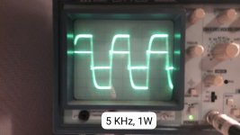
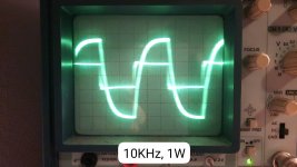
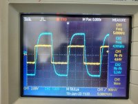
this is the result of the square wave.Can you post the 1kHz 1W square wave response?
Attachments
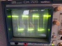
Good, try to tame down that overshoot by adjusting the input stage RC network, by increasing the C.
Be sure to load the speaker output with an 8R load for this test.
Be sure to load the speaker output with an 8R load for this test.
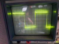
Much better. You may want to add a Zobel across each amplifier output for using actual speaker loads.
The usual 0.1uF pp film in series with 10R 3W or 5W should work ok.
If there's no room inside the chassis, the Zobel can be external, across each amplifier output.
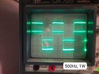
How does a 1W, 100Hz square wave look into a dummy 8R load?
The usual 0.1uF pp film in series with 10R 3W or 5W should work ok.
If there's no room inside the chassis, the Zobel can be external, across each amplifier output.
How does a 1W, 100Hz square wave look into a dummy 8R load?
Last edited:
I will test the 100Hz tomorrow.
Are there more frequencies I should test?
Because i need to clear the setup from the table when I am done meassuring.
And what do you mean with a Zobel?
Do you mean the RC series network?
Are there more frequencies I should test?
Because i need to clear the setup from the table when I am done meassuring.
And what do you mean with a Zobel?
Do you mean the RC series network?
Yes, a Zobel is a resistor and a capacitor connected in series.
Then connect that combination in parallel with the 8 Ohm tap speaker output.
Use a 0.1uF pp film @ 100V low inductance (extended foil) capacitor
and a non-inductive 10R @ 3W or 5W resistor.
It helps the amplifier to see a more resistive load at high frequencies,
so the amplifier is more stable, and the overshoot is tamed.
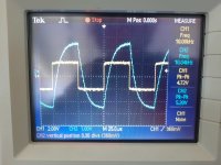
It dit take a little longer for me to do the tests.
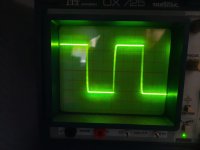
But with the zobel network, this are the results
But with the zobel network, this are the results
Attachments
-
 Afbeelding van WhatsApp op 2023-06-08 om 16.16.27.jpg205.4 KB · Views: 60
 -
 IMG-20230608-WA0018.jpg168.1 KB · Views: 55
 -
 IMG-20230608-WA0019.jpg187.4 KB · Views: 59
 -
 IMG-20230608-WA0020.jpg117.3 KB · Views: 55
 -
 IMG-20230608-WA0021.jpg206.1 KB · Views: 57
 -
 IMG-20230608-WA0022.jpg147.2 KB · Views: 55
 -
 IMG-20230608-WA0023.jpg150.3 KB · Views: 62
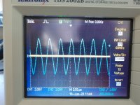
Looks good, and the no-overshoot square wave is better.
If you are inclined to experiment further, try cutting the value of C in half.
Around 0.047uF, depending on what values you have around.
If the 10kHz square wave is still monotonic, that will be good.
If you are inclined to experiment further, try cutting the value of C in half.
Around 0.047uF, depending on what values you have around.
If the 10kHz square wave is still monotonic, that will be good.

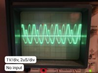
What is the amplitude of the hum? Presumably it is at 50Hz or 100Hz.
Show the hum waveform with no signal input, and the input jack shorted to ground.
Show the hum waveform with no signal input, and the input jack shorted to ground.
the hum is indeed 50Hz. when I am going to build the amplifier for real,
I am going to use bigger capacitors for my power suply.
at this moment I am using a 47uF cap.
I also notiched that my tubes are glowing blue on the inside.
Is that normal?
I am going to use bigger capacitors for my power suply.
at this moment I am using a 47uF cap.
I also notiched that my tubes are glowing blue on the inside.
Is that normal?
Attachments
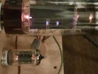
If using a capacitor input filter and tube rectifier, make sure the tube can handle the input capacitor.
The blue is ok.
The blue is ok.
leemhuis01,
1. If your hum is 50Hz, then:
It is Not from a Full Wave Rectifier (from 2 diodes and a center tapped secondary circuit),
And it is Not from a Full Wave Bridge Rectifier
And it is Not from a Full Wave Doubler Rectifier Circuit
Full Wave Rectification results in hum that is 2X the mains frequency.
50Hz mains: 100 Hz full wave hum
60Hz mains: 120 Hz full wave hum
Your 50Hz hum is from something else.
Ground Loops (Input connection to signal source or to signal generator; Filament to Cathode leakage current; etc.)
Magnetic Coupling from Power Transformer to Output Transformer
Half Wave Rectification (or a Really Very Bad balance of Full Wave rectification, like one alternation direction is busted)
One high voltage secondary lead near a tube grid wire or tube grid part (RC coupling circuit, etc.).
Watch out for Magnetic Steel Chassis once you go from breadboard to Chassis (Aluminum does not transfer magnetic interference).
Another 'source' of mains hum is the ground loop between the amplifier and your scope/sound card.
Both are plugged into the mains power, any leakage currents are at the mains frequency, and show up when looking for small amounts of hum.
Good luck finding the source of the hum.
Troubleshooting Pays Off.
2. Often, some blue glow is normal.
Sometimes it is not.
Your picture does not have enough detail to show the difference.
Last edited:
You will need another resistor ot ground piint at the 10 ohm cathode resistors so that the plate current has a place to go.
The grid bias can be around -30 volts for this tube.moving this with a pot between -30 to -40v will balance the tubes.
The grid bias can be around -30 volts for this tube.moving this with a pot between -30 to -40v will balance the tubes.
I will make better scope immages this week.
I am taking my amplifier to school.
There they have better equipment for these measurements.
my scope has some trigger issues, what makes things a little difficlult.
There I will make some scope pics that are a little bit better.
Alse 2 of my teachers are going to help me then.
There I can also do FFT to see wich frequenties are present in my hum.
And I can test the frequency response of my amplifier
So, today i have made some pictures using my schools equipment.
The square wave tests are looking pretty much the same after changing the capacitor.
But i have a better picture of the hum that my amplifier has.
At the speaker connection i see a hum with a frequency of 2,75 Hz.
I need to search where that comes from.
But then i did also look what my EL34 has as input.
And with no input, there is a 300KHz signal (8Vpp).
That should not be there, as far as i know.
I also did a FFT (fourrier analyse), there i saw that i also have some harmonics of this frequency.
There I saw that 600, 900 and 1200 KHz are present as well.
Should this be a problem with the feedback?
Because at this moment, i dont know where i should look for this problem.
finaly, i tried to measure here and there with my teachers.
And when we placed the oscilloscope on the 2 speaker wires,
the hum almost dissapeared completly. there was only 20mV amplitude left.
Attachments
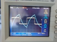

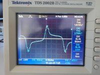
I can't speak to the hum issue, but those square waves are too rolled off. The amp is really rolling off on the high end. What you had the first time was better, IMO. A little overshoot on a 10K square wave is fine. There's is no ringing so the amp looks pretty stable. I would either remove the zobel network as not necessary or reduce the phase lead cap across the feedback resistor.
- Home
- Amplifiers
- Tubes / Valves
- Tube Amplifier Design