I read in Stereophile that one of the reviewers likes to connect his headphones to the speaker's binding posts of his tube amp. Is this generally possible? Do you have to use a special adapter or resistor modification?
I found this from Pioneer back in the 70's, it's called the JB-21: Pioneer JB-21 headphone juction box - Vintage Audio World.com
I found this from Pioneer back in the 70's, it's called the JB-21: Pioneer JB-21 headphone juction box - Vintage Audio World.com
It's ok to directly connect the phones if the amp has grounded outputs (most headphones have a common ground).
You may hear hum or noise with a tube amp and headphones, though. Some use series resistors to reduce the
audibility of noise, but this can affect the sound quality from the headphones. Also there is a danger of overdriving
either the phones or your ears.
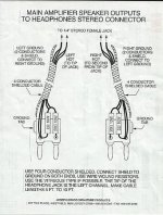
All you need in the box is a phone jack, series resistors if used, and an optional switch to turn off the speakers,
along with the needed connectors for the amplifier (and for the speakers, if using the switch to turn them off).
Something like this one: My Cable Mart - Five-Way Speaker Switch Box with Headphone Jack (4 or 8 Ohm)
You may hear hum or noise with a tube amp and headphones, though. Some use series resistors to reduce the
audibility of noise, but this can affect the sound quality from the headphones. Also there is a danger of overdriving
either the phones or your ears.
All you need in the box is a phone jack, series resistors if used, and an optional switch to turn off the speakers,
along with the needed connectors for the amplifier (and for the speakers, if using the switch to turn them off).
Something like this one: My Cable Mart - Five-Way Speaker Switch Box with Headphone Jack (4 or 8 Ohm)
Last edited:
What is the model of your amplifier?
What is the model of your headphones?
There is no one answer for an unknown amplifier, an unknown headphone set, etc.
How to connect, and what auxiliary equipment depends on the above.
Careful:
You may blow up the amplifier (needs a proper load).
You may blow up the headphones.
You may damage your ears.
You may hear hum and noise.
A valve amp needs a load on it to perform properly and not get damaged.
If the amp is 8 ohms and your headphones are 8 ohms then there is no problem.
If the headphones are high impedance you might need an 8 ohm resistor across the amp output.
If the amp is 8 ohms and your headphones are 8 ohms then there is no problem.
If the headphones are high impedance you might need an 8 ohm resistor across the amp output.
The schematic above is a priori the best way to proceed. The divider ratio has to be tailored for each amp/headphones to get the proper attenuation. The 30r resistors in serie are not strictly needed however and in my experience many headphones will sound better with these omitted.
I will second recommending the schematic posted above. If the amp is really powerful and has a ton of gain, I would increase the attenuation.
Koifarm,
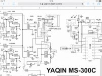
1. The only load to the 300B is 680 Ohms in series with the headphones.
I hope you do not use a phono cartridge, and then the phono plug from the turntable arm comes partway out from the phono preamp input.
That will cause the 300B to produce maximum voltage square waves from complete cut-off to maximum current, and everything in between.
Or any other mistake that causes the 300B to produce such large square waves.
Hard on 300B, output transformers, headphones, and ears.
What works for you for several years will not work for 5 minutes for someone else who
has a bad day with maximum amplitude signals.
2. I vote for Post # 6.
"Make things as simple as possible, but no simpler" Albert Einstein
6A3sUMMER,
i know the 300b schematic is better. It divides the voltage about 20 times.
The schematic in post 6 divides the voltages about 5 times.
i know the 300b schematic is better. It divides the voltage about 20 times.
The schematic in post 6 divides the voltages about 5 times.
1. Make the voltage divider impedance back to the amp be a proper load.
2. Make the voltage divider ratio whatever you need for the headphones:
Large enough ratio so you do not hear hum and noise in the headphones,
Large enough ratio so you do not ruin your ears if you turn the amp volume all the way up,
Small enough ratio so you can hear the quiet passages of your music in the headphones.
3. There is no one divider ratio that "fits all".
Amplifiers are different.
Headphones are different.
Music sources are different.
4. You can have just about any divider ratio you need and want, and still provide a proper load to the amplifier.
Just takes some study and a little work.
How does that sound?
Last edited:
The other big advantage of the schematic in post 6 is that it offers a low impedance output (minus the 30r resistors). A high output impedance will mess up the frequency response of many headphones. Manufacturers voice their headphones for a near zero output impedance these days.
If you have a non-negatrive feedback amp, and you lightly load an output transformer, the bass frequency response may be reduced relative to higher frequencies, versus when you properly load the output transformer.
No load, the transformer inductive reactance is the impedance the output tube sees at low frequencies, and that impedance rises with increasing frequency.
Proper load, the transformer inductance in parallel with the output load (which is reflected back through the transformer according to the square of the turns ratio), is what the output tube sees.
That reflected load appearing at the primary, helps to partially swamp out the primary inductive reactance.
That creates a more constant load versus frequency to the output tube, until either the leakage reactance or the distributed capacitance, or both change the impedance that the output tube sees.
A bit complex, but that is true. (and 'pun intended')!
The schematic in post 6 divides the voltages about 5 times.
Actually -21dB divides the voltage by about 10 times.
-21dB K factor for voltage = 10^21/20 = 11.22
Z1 = 8Ω
Z2 = 32Ω
R3 = 2√Z1*Z2(K/K^2-1) = 2√8*32(11.22/11.22^2-1) = 2.87Ω
R1 = Z1(K^2+1/K^2-1)-R3 = 8(126.89/124.89)-2.87 = 5.26Ω
R2 = Z2(K^2+1/K^2-1)-R3 = 32(126.89/124.89)-2.87 = 29.64Ω
It's called a T-pad attenuator. Just simple math.
Z1 = 8Ω
Z2 = 32Ω
R3 = 2√Z1*Z2(K/K^2-1) = 2√8*32(11.22/11.22^2-1) = 2.87Ω
R1 = Z1(K^2+1/K^2-1)-R3 = 8(126.89/124.89)-2.87 = 5.26Ω
R2 = Z2(K^2+1/K^2-1)-R3 = 32(126.89/124.89)-2.87 = 29.64Ω
It's called a T-pad attenuator. Just simple math.
Last edited:
The other big advantage of the schematic in post 6 is that it offers a low impedance output (minus the 30r resistors).
Do not use the circuit without all of the components. There is no effect on the high frequencies. T-pad attenuators have flat frequency response.
But headphones aren't flat impedance wise. It's actually in the low frequencies that you will have the most deviation usually if your amp output impedance isn't close to zero. For example a pair of hd595 is mostly 50ohms but goes up to 250ohms at 100hz. There is no point to match impedances here.
See attached for reference, from Joe Grado.
See attached for reference, from Joe Grado.
Attachments
Well, the Grado circuit is probably as overrated as their headphones are. But we can agree to disagree right?
But headphones aren't flat impedance wise. It's actually in the low frequencies that you will have the most deviation usually if your amp output impedance isn't close to zero. For example a pair of hd595 is mostly 50ohms but goes up to 250ohms at 100hz. There is no point to match impedances here.
See attached for reference, from Joe Grado.
- Home
- Amplifiers
- Tubes / Valves
- Tube Amp for Headphones