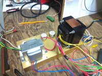
The amp will be a Bassman AA864 (with an AB165 preamp). Have it working fine on a breadboard, and want to stuff it on this 5-1/2" x 11" chassis. Eyelet board is 11" x 2", will run the entire length underneath. Xfmr cores are positioned perpendicular. Pots in front, AC, fuse, spkr jack & bias pot in back. Anyone see any major problems with this layout? Wire lacing will be tight (and critical to avoid hum). Thanks!
Attachments
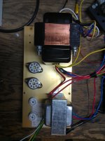
Looks like it's going to be pretty tight. You might have some interactions between the output transformer and the preamp section as the output transformer will likely be sitting over top of your gain stage components. I usually like to keep anything away from the gain stages. I don't know how well shielded your output tranny is, all that power from the tranny might "bleed" into your gain stages then amplified, might result in feedback. You can try it where it is and if there is no issues, great. If not, you can always relocate it.
Cheers
Cheers
Apply power to your power transformer with a load.
connect voltmeter to output primary and see if you can move the output transformer to ward your power transformer without picking up hum. You could also use headphones connected if you don't have a sensitive volt meter.
connect voltmeter to output primary and see if you can move the output transformer to ward your power transformer without picking up hum. You could also use headphones connected if you don't have a sensitive volt meter.
I've been trying to use a small chassis, and am having trouble figuring out where to put the potentiometers.. All the real estate near the tubes is full of resistors and caps.. The area in the back near the transformers is all open, but I don't want to run my signal directly under the power supply components. I'm about to give up and go to a bigger chassis..
So, make sure all your controls will fit.
So, make sure all your controls will fit.
Great comments thanks! Wicked1: I had to relocate my vol pot on a Princeton clone to reduce hum, moved it so that shielded runs in and out of the preamp were the shortest.... Mike567: I will test OT and PT orientation under load - as they were (and are) wired to my breadboard when I took the pic. Poacher: Shouldn't the chassis shield the eyelet board from xfmr RF?
Poacher: Shouldn't the chassis shield the eyelet board from xfmr RF?
Not necessarily. Even if did, the output tranny is still right beside the preamp tubes. Just good practice to keep unwanted signals away from the preamp tubes. You will notice this as a common practice among commercial manufacturers. But, since this is DIY, you can try it where it is. Maybe you won't have issues. Reading from your last post, it might already be soldered in. You can always move it away, like mounting it to the speaker frame or in the cab somewhere.
Just added a tone stack to my breadboard Bassman (two pots, ala AA763 Concert Amp), sounds great, but have a question: I want a lot of headroom on the first stage (to allow for extra gain from pedals), so am thinking of giving it more gain (via more plate load), but bias it on the cold side (cathode resistor), then tone stack and vol pot to 2nd stage, bias it hotter, then a 2nd vol pot to the PI/Pwr section.... Does this make sense? Give me more control of the amps potential? Thanks!
Hi Guys
Building a tube amp into the smallest chassis possible is usually a mistake - just look at all the early/mid mesa stuff: too small + poor layout + bad design decisions = a good oscillator.
It is easy to make the amp dead quiet and have great note articulation, just by following correct wiring methods. TUT3 shows how and there is a chapter about the Bassman showing both a tube-recto version and a conventional form.
For pedal compatibility, better to stick with the stock fender input stage. if it overloads, pad the input like they did - that's what the second jack is for - or use a low-mu tube. You would not "maximise gain to improve headroom", rather, you would do the opposite.
Note also that Fender's layout used a rather large eyelet board that occupies nearly the entire chassis interior. This is not necessary considering the simplicity of the circuit. However, some spaciousness in the layout is good inasmuch as parasitic capacitance is reduced. A more careful layout allows proper placement of the filter caps for each circuit allowing proper grounding to be implemented. Random grounding ala Fender is joke and contributes to their noisiness.
The bias pot should not be on the rear panel. Rather, there should be a separate bias control for each tube mounted on the tube plane of the chassis beside each tube. The rear panel should have meter jacks allowing safe ground-referenced monitoring of each tube's idle current using current-sense resistors. TUT3 shows all of this, as well. This position for the bias pots makes it as accessible and as protected as the tubes are.
Have fun
Next amp I build will be on 2 or perhaps 3 chassis.
Power supply
Preamp
Power amp
I really like a layout somewhat like the SVT, with preamp chassis on top with tubes sticking down ala-Fender but power amp chassis on the bottom with tubes sticking up. In-between: fans. This puts the preamp controls accessible at the top corner, and the heavy transformers at the bottom.
Am I missing something here or what? I am looking at the schemo of both AA864 and AB165 and they both will need four 9-pin sockets. You only have two on the proposed chassis. Even if you eliminate the bass input there will still need to be three. To have only two 9-pin sockets you will have to eliminate the bass input plus the stage just before the PI.
You are right about that; with only 2 stages for the phase splitter and 2 for the preamp perhaps he figures he doesn't need to mix the two channels (having just one) but it's not going to have much gain or drive the splitter very hard. Maybe if he uses a 12ax7 for the splitter instead of 12AT7.
Hi Guys
The standard two-stage fender pre driving any power amp provides a very nice sounding amp. Were you to place a second level control after the second preamp stage, you could drive that stage fairly hard, achieving mild overdrive within the preamp and then controlling how much of that gets to the PA. You can certainly overdive the PA quite hard with preamp levels up high.
Alternatively, moving the EQ to after the second stage gives a more vintage Bassman/plexi tone. Similar drive capabilities.
In either case, the amp is very pedal friendly.
Adding the third preamp tube gives one more flexibility for tone and overdrive, even adding a single gain stage.
Have fun
Thank you Struth for the info. I was merely pointing out that he didn't have enough sockets for those preamps. Absent that mid-amp stage it really isn't one of the two preamps he was emulating. You're absolutely right,it is amazing how much gain you can achieve with only two 12ax7 stages! So much to learn. I guess that's why we have two ears and only one mouth!
I'm glad you guys figured me out for me....! Yes, only one 12AX7, 2 gain stages, one input. Yes, not exactly the Baseman preamp, but Fender none the less. Without the tone stack I was able to square wave the power section. Splitter is AX7 also. Plenty of gain! Haven't decided on a chassis yet, still playing. Will move the tone stack to post 2nd stage, see what that sounds like. Thanks for all the comments!
Just remember adding a three knob tone stack will add insertion loss and you will lose gain. How much depends on the design of the stack. If you can get by with a simple tone control(one cap. and pot) this will help you keep the gain you have generated. Higher overall resistance like a three knob stack generally will have greater insertion loss.
- Status
- Not open for further replies.
- Home
- Live Sound
- Instruments and Amps
- Tube amp chassis layout proposal