I've seen this supply design on and off and never really understood the purpose and the result of connecting the center tap between the capacitors this way. Here's a couple of examples-
Attachments
Last edited:
I wonder whether it is significant that if you multiply 160VRMS by two, then put that waveform through an ideal diode with no forward voltage drop and no series resistance, you get 452 volts DC. Pretty close to the DC voltage number printed on the schematic. Is it a coincidence?
_
_
Attachments
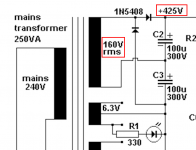
No coincidence. Its a classic voltage doubler. The top right hand diode and cap derive the 'plus' voltage and the lower cap and left hand diode derive the 'neg' voltage. Those polarities are referenced to the lower connection of that winding. Add the two voltages together... voila.
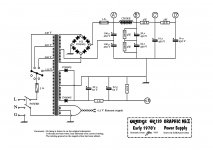
These two circuits are completely different. The left circuit (Oradge) with diode bridge is a normal full wave rectifier.
The only exceptional detail is that the center tap of the secondary is connected between the two first 100 uF electrolytics.
The DC-voltage at the ct of the secondary is half of the rectified output voltage and therefore this connection ensures that the middle point of the electrolytics is set at the half potential. Similarly the potential of the two 32 uF electrolytics after the choke is set by two 100k resistors.
So, nothing functionally special.
Last edited:
> The left circuit ... this connection ensures that the middle point of the electrolytics is set at the half potential.
And the reason is: the supply makes more than the 450V rating of a single electrolytic cap. (Yes, we can get 500V, but this rig is probably more.) Film caps cost too much. We "stack" two 450V electrolytic caps to get ~~800V rating. But they will NOT "split" the voltage equally; different leakage.
One way is a heavy 2-resistor bleeder passing much-more than cap leakage current. Look around, you can find some. In fact the second (screen) filter does just this. (There's another way but they didn't go that path.)
But if you bring out a PT CT with this topology, you get HALF! DC voltage on the tap. The caps can NOT get more than half total DC voltage each. Neat trick.
As said, the other one is very different, though does intrinsically force both caps to have of total VDC.
- Status
- Not open for further replies.